 So I built a holocron a while back, starting from a kit (of which I ended up using very few parts). I also wrote the build up as an Instructable, and included -- free of all restriction -- all the SVG files I had created.
That Instructable caught the eye of a fellow RPF member, and thus I'm back in the holocron business, but this time with a completely custom design.
The original Golden Armor holocron was twelve pieces of laser-cut acrylic. Apparently this was how the three holocrons built for Lucas (for some sort of game promo) were done as well. Golden Armor's scheme wasn't bad; sand the internal panels lightly to diffuse the internal lighting better, and glue the outer panels corner-edge to corner-edge, filling the resulting void with Bondo.
 But even on my first I thought I could improve that a little. So I threw out the internal pieces and laser-engraved new ones, then laminated those up with yet a third layer, this the "circuitry" layer inspired by the panel lines on the Millenium Falcon consoles. That gave a very nice depth to the holocron, even when the internal lighting was off.
To finish the Golden Armor shell, I used small pieces of acrylic square rod, gluing them along the edges before assembling the whole thing.

Thus my new shell design. And, yes, it was a lot easier to line up the pieces. But it could be better yet (also, the location of some of the splices would make them hard to clean up).

So first they have corner passes. These are because the laser has a slight radius, and tends to melt the plastic a little on inside corners; left without correction, the corner will be slightly rounded and thus the intersecting finger won't quite fit.


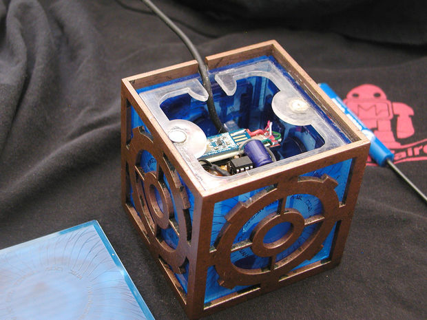
And of course the new interior pieces interlock as well. My first run (for which I purchased the wrong material, which is why it lights nicely but doesn't contain any of the engraved or interior detail) they are simple staggered edges. Assuming the new snap-fit interlock works, however, they will get those fingers.
What I haven't quite worked out are the last pieces that hold the internal circuitry, and provide a place for magnets to hold down the lid. I'm also wondering if there is a way to deal with the "circuitry" layer so it doesn't have to be carefully glued to the back of the diffusor panels.
And this is where the design rests, until I can get out to Tap Plastics for the right acrylic, then manage to find a slot on the calendar when one of the laser cutters is free.

(The first run, with the wrong kind of diffusor panels), lit for test purposes with one of my Cree).
No comments:
Post a Comment