It's been a bit crazy (the theater business is like that, and so is the starving artist lifestyle. The combination....!)
When I have time to post properly, I think it might entertain some to look at the microphone setups I've worked with (my designs and others) on actual stage shows. Very often, these are driven not by studio aesthetics, but by lack of equipment, lack of space for the orchestra, lack of anything resembling an A2 or other person who can be trusted to get them in the same position from night to night, and of course from lack of time.
The unfortunate reality is that when most companies produce a musical they forget that the word music is right there in the description. So there is eight thousand dollars for a rental set. Six lighting technicians working for two days to get the lights to look great. But not a dollar to replace aging microphone elements -- some shows, you can't even get fresh batteries!
And as far as the actual need goes: in many productions, the band will be too loud to begin with. You are fighting to get control of them so you can get the singers heard -- without simply putting the singer's microphones up to 11, which sounds horrible and hurts ears and is really no solution at all. Make friends with the vocal director. Get a rapport and a dialog with them. Not only do they often have more pull with the director, they are also the artist you are trying to support; the person who knows what they were trying to achieve vocally from moment to moment. Look to them for advice as well as for support.
A small but unfortunate number of conductors, on the other hand, consider their job starts and ends with the pit. A band can get insular; they have their own call time, they don't share the dressing room, they weren't involved in most of the rehearsal process. They show up on their own schedule and keep to the pit through the show. Sometimes you have to get down there and strike up conversations and act as a gentle reminder that there is a SHOW up there on the stage floor above them.
Still, the majority of conductors understand that they work within the total sound of a show, and are not just happy but eager to have trusted ears outside the pit that can tell them if the underscore is at an appropriate level.
Practically speaking, then, it is rare that the band isn't loud enough. If volume were all that there were in the world, you wouldn't need to do anything further. Here is where the hard sell begins; with judicious mic'ing, you might increase the total VOLUME slightly, but you achieve a much better placement, tone quality, and focus.
Also practically speaking, monitors can never be too loud for actors. They will always want more. More often than not you end up with stomping levels of piano -- a sound that completely distracts from the orchestral blend desired -- because the actors whine if you try to turn it down.
All of this often ends up with you cramming what microphones you can spare in what spaces you can find just to lift up the actual tone of the instruments from the wash of reflected and reverberant sound. In this, however, even a single mic gives the final orchestral sound something positive it didn't have before. So even if all you have is a single Radio Shack PZM, and the only place you can stick it is on the actual side of the pit, it may still be a net improvement to the sound of the show.
And, at that, it is a great chance to experiment; trying out different mics, different placements, messing with EQ to see what elements you can bring out.
When I come back to this, I'll have some scans of the drawings from actual productions in which we did pretty much that. Perhaps I'll remember to photograph a few set-ups next time I make them, too.
Wednesday, March 30, 2011
Wednesday, March 23, 2011
Pulling Maintenance on the Machine for Living
So I'm trying to clean house. Which is more about re-arranging; the usual method of "stick all the loose stuff in a closet and then mop the floors" doesn't work when there is more stuff than will fit in the available storage. These units are so small, indeed, that even adding more storage spaces (shelves or cupboards or wardrobes or whatever) is also not a simple solution. There is too little wall space, too little floor space, too little total room.
I've seen a couple of the other tenants add giant free-standing cabinets. That managed to get almost everything off the floor and out of sight, but it made getting across the apartment like navigating a claustrophobic wooden maze. Since to my mind the whole point in putting stuff "out of the way" is to allow easy movement across the apartment, unobstructed sight-lines, and a feeling of space and openness, any scheme that requires you to turn sideways in order to get past the shelves is NOT on.
Plus, even if there was a huge closet, you'd end up with the things you need buried so deeply it was not just hard to get at them, it would be hard to remember you had them in the first place. This goes double for renting storage space off-site. I don't own things just to own them. I own tools. The vast majority of those tools will get used within the space of a month.
And that makes the storage even more complex. The point is not to get things tucked out of sight...what I am trying to achieve is having the electronics parts and soldering station, the drill press and grinder, the monitor speakers and keyboard, all where I can leave them set up for a couple of weeks or more as I work on an electronics project, a prop, or a composition.
This isn't a bad apartment if what you want to do is live in it. The "Machine for Living" idea enunciated by Le Corbusier carries with it the same flawed assumption behind so many stores like Orchard Supply or Radio Shack. And that is an assumption of domain. "Work" is done at a work place; a large factory or lab that has an owner; a place you go to spend the productive day. "Home" is where you go with your time off, to recover between sessions of productive work. You might chose to "Play" some at home by doing similar things to that which is done at the factory, but it isn't "Real" work.
The denigration is still there when you have a little shop -- if the shop is more like a garage or a rental. Although the more you move out of your designated "eat and sleep" area, the more it is allowed that you might want to use power tools. It even denigrates those activities that do not require a large space, 220v power and forced ventilation, by labeling many of those productive tasks as mere "crafts."
A problem with this attitude is that today's economy, due in part to the technologies now available, makes more and more use of the productive efforts of home work. Entire industries are on a cottage model, with the largest workshop being a shared-use rental by two or three amateurs who pooled their money.
There has always been an element of this in theater, which has the pressures of needing non-mass production items on a schedule and on a budget that precludes many of the usual suppliers. Theater has always been made at least in part in people's homes. In my own concentration, sound effects are created, light plots designed, even bands recorded in home studios and small drafting spaces. Props are also built, costumes stitched, special effects worked out...and even bits of scenery built in spaces that are really far too small for that!
I am by no means a comic book artist but this is the space they need to work; a large drafting table, a shelf of reference books, perhaps a space to take reference photographs, and a good internet connection. A professional artist will usually have a room dedicated as a workshop but more is just silly. Ditto for a writer. Add space for a piano for a composer. None of these need a garage to work in.
These are all industries, then, productive industries that take place in that space that is designed for and honed over the years to support an entire other class of activities. The design of a typical apartment is a place to sleep, to cook small meals, to shower, to store clean clothes. There's space to read or watch a movie or play a game in the few hours of personal time between work and sleep. There's closet space for the surfboard or the gardening tools or whatever it is you dedicate more hours to on the weekend.
Building a theatrical prop, designing circuitry, or even, yes, writing a novel has to be retro-fitted, crammed into a space that was never designed to hold it. When you've got a larger apartment or house to play with it can be easier to make the fit (although you are always fighting the architect's original vision; that spare rooms are playrooms or guest bedrooms -- they don't have ventilation, power service, loading doors, water....
For people in my situation the crunch is acute. The era of the cheap loft is over. Work-live spaces were a great idea but they got taken over by people who WORK elsewhere and PLAY at being an artist on the weekend (if ever.) The death knell was when the people moving into the loft spaces started complaining to the zoning boards about all the power tools being used in the adjoining spaces.
If I were smart, I'd surrender partially. I am in no way likely to earn enough soon to afford to take my messier work elsewhere. So the best option is to try to limit the activities I do. They are, against the expectation our society still seems to hold about the divisions between work and play, mostly paying activities. When I compose, it isn't to relax after work; it IS the work. It is the day job. It is what pays the rent. But I don't believe I can support that many different things without needing more apartment to do them in.
Which in a way is a blessing. I can't spare enough ME to do all those different things, either!
Wednesday, March 16, 2011
"We Need Four Mics"
Once again, I had a client walk up to me and say "We need four mics."
The setting for this is a multi-use rental facility (a lovely old church converted into a theater). I am the house technician, and in many of these cases I'll also be their front-of-house mixer for the show.
There's sometimes a tech rider, but it rarely has any detail. What the client says when they come in the door doesn't match anyhow. And the band isn't due until later (and what they say will be different from the first two!)
So all I've got is the director or assistant producer or something standing on a bare stage, saying "We need four microphones."
Usually, I will ask "What are they for?"
That's when the client blinks, and parrots "We need four mics." And that's when I realize something horrible. Not just that they don't know any more. But that they don't know there is more to know.
Mics are a form of MSG to these people. You count the number of performers, and that's the number of "mics." You add "mics" to each performer, and suddenly they all sound great and you've got a show.
Fortunately, the band usually has a bigger clue. Unfortunately, when the band gets there, even before they've finished setting up the client is on my case saying "We need to start sound check now."
Oh, sure, I could have set up "four mics." Our stage is sixty feet wide and forty feet deep. There is only one snake. It takes up to sixty feet of cable and ten minutes to be able to plug in just one mic -- in, of course, one specific spot. So I could go ahead and set up "four mics" in a wing, or across the edge of the stage, but that would put me no closer to having them where they need to be.
We have a collection of stands and tripods, plus some specialty stands for stuff like mic'ing a guitar amp. So that has to be figured out too; how do the "four mics" need to be positioned and what sort of hardware do they need? Again, I can guess, but if I guess wrong all I've done is waste time -- and I'm still not any more ready for "Sound check."
("Sound check." I am convinced the client saw someone say that once in a TV show or something. So they know they are supposed to have one, although they have no idea what it is. And they'll stand around demanding we start "sound check" with all the evident self-satisfaction of a manager doing a difficult job well.)
But all that pales before the question of application. The nature of the thing being mic'd determines the best choice of microphone. Not everything in the world is best served by putting a generic dynamic in a stand in front of it. Mic'ing a drum kit alone is an art, involving a variety of mics on specialty hardware in very specific positions.
So, "We need four mics" is, in this context, pretty much the same as going online to Amazon.com, getting hold of a customer service rep, and saying "Send me four books." Don't tell them what subject or author, don't even tell them where you live! Just demand "four books" -- and get upset later when sound check goes badly.
What this is, and I'll write a long rant on it eventually, is an error of compass. When you are dealing with a sound technician, especially one who is also going to be your front-of-house mixer, you want to leverage their skill set.
Don't tell me "Four mics" and think that is either necessary or comprehensive information. Tell me "Three-member jazz combo with baby grand, set up Stage Left." then I know how many mics, and what kind, and what hardware, and how to place them.
In all fairness, often enough the clients who say "Four mics" aren't particularly skilled musicians, and are doing some potluck of a talent show where there are fifteen different acts and no specific common layout. If that's the way the wind blows, I'll get them four of my most durable dynamics and set them on straight stands across the front of the apron....with lots of extra cord and nice big clips so they can remove the mics easily. And if I have the gear on me, compressor set as a hard limiter so they don't blow out my speakers (and audience eardrums) when they chose to blow into to mic or start screaming into it at 1 mm distance.
This is an old post being transferred from a previous blog. I may have learned more about how to anticipate, compromise, and more importantly not be confrontational since then. Or perhaps not! The idiots are still out there, and of course the sound remains the same. At least now with a kit of personal snakes, cheap condensers, and the newer programmable sound boards I can come up faster with something that will probably work.
For those (few!) who have been coming here for sound design and theatrical design, I am providing this post also as an excuse to collect direct links to my earlier blog entries.
The "Care and Feeding of Wireless Microphones" series:
The Basics of Mic'ing a Cast
The Basics of Mic'ing a Cast II
The Basics of Mic'ing a Cast III
The Basics of Mic'ing a Cast IV
A Few Simple Rules for Wireless
The Two Nations of Sound Reinforcement
Theatrical Sound Design series:
So What is Theatrical Sound?
The Basics of Sound Design
The Basics of Sound Design II
Six Simple Rules for Getting a Good Voice-Over
It's Alive, ALIVE...!
Well...at least it has a pulse.
I made a little more progress with AVR programming; now I can run a timer in hardware mode, without a single line of program code (even an interrupt). Right now one of the last of my working chips is pulsing an LED; Timer0 is hardware driving the pin directly in PWM mode, but a routine running in the main() program loop is incrementing and decrementing a value to smoothly brighten and dim the LED over time.
But I'm not going to talk about that. I'm going to back up, because I realize I skipped over some of the basics of programming an AVR.
Start with the Arduino.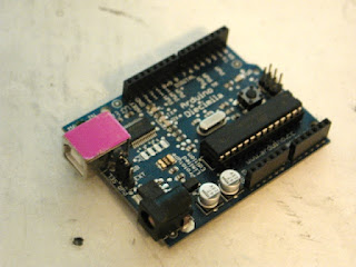
The Arduino is the artist's micro. It is very much non-geek. You can use an Arduino without picking up a soldering iron. You can use one without knowing really anything about programming!
On the hardware side, most Arduinos and clones come pre-assembled and tested. A naked Arduino isn't that interesting to a non-geek, though. All they normally have is a single LED just so you can upload the "hello world" program and confirm the thing is working.
But this is why there are shields. Many shields also come already assembled. There are shields with MIDI jacks on them. Shields with LCD displays and buttons on them. Shields with relays on them. Shields with motor drivers on them. Shields with full-color touchscreens and tiny joysticks on them. Shields with Xbee wireless links, Ethernet jacks, MP3 chips, lithium batteries with charge circuits, even NTSC television output on them.

It is literally as simple as taking the shield and seating it on top of the Arduino. Sticking new RAM in a computer is much harder than that.
Oh, yeah, and you can make your own shields...as scratchy as the perf-board shield I posted in a previous entry, to slightly nicer assemblies on pre-made proto-board as on the right, to professional printed PCBs made by one of the various mail-order fab houses that have sprung up over the last few years.
The point is, the Arduino is designed to get you up and doing what you need to do; remote data logging or adding a startup chime to a motorcycle or controlling a music synthesizer from a wii remote. The heavy lifting has already been done for you. And the same is true of the software.
You can "program" on an Arduino in Script Kiddie mode, in Magic Spell mode; knowing nothing about how the software works or even (especially if you are using library functions) what it looks like.
If you can install a computer game, you can get an Arduino working. I've had a remote control on an old television that was harder to figure out.
Not to disparage the Arduino project, of course. Much of what makes it so easy to do so much now is because of other users; users who started out as total beginners and figured out how to do something, then took the next step and made up a library or a shield and put it back out into the community under the same open-source, open-hardware rules.
And if you want to geek out, there are plenty of places to geek out. Starting with assembling the kit yourself. Sure, you only save a couple of bucks, but it does give you a nicer sense of accomplishment.
It isn't that easy for me to get a good perspective on some of this. I've had a soldering iron in my hands since I was six. I used to cobble up all sorts of basic tricks with LEDs and strobe lights and audio-frequency oscillators -- especially when I was hanging out at Star Trek and science fiction conventions. But I was basically cheating...never did learn much of basic electronics. Even today I have to look up Ohm's Law. Most of the stuff I did then was pretty much Magic Spells; wire up the 555 the way Forrest Mims drew it, and if I was lucky, it worked.
Perhaps another way of putting this is it is recipe-based cooking. When you first cook from a recipe, you are scared to change a single ingredient. Later, you are out of eggs, you substitute oil for butter for health reasons, and you don't bother to measure an exact teaspoon but just toss in a pinch that looks about right.
In electronics and programming this is a good way to get acclimated. Take a working code, or circuit, and tweak some values, mess around with substitutions. You are trying to get a sense of what the different parts are doing by replacing them or taking them out. Most of it will be trial and error.
But at some point you need to move on to grasping the underlying theory. And I am a great fan of manuals. I say -- play first. Get your feet wet, mess around, get creative. THEN hit the manual hard to try to figure out why taking out that one capacitor made the amp stop working, or why changing "A = 2" to "A = 3" made the LEDs chase in the other direction.
At various points, take the time to dig down and read the whole manual (or datasheet, or tutorial, or whatever) from top to bottom. You can still skim over the parts you really aren't grasping, as well as the parts you are sure you know by now, but try to at least skim them. It is there that most of the "Ah hah!" moments come...as you stop at last on something you'd glanced over before, and realize the solution to Why It Isn't Working Since I Changed It is in that chapter.
Enough digression.
I've mentioned that the heart of the Arduino is a chip made by ATmel. That it is a computer-on-a-chip; everything but power regulation and the actual buttons and displays is already included. Again, the heavy lifting has largely been done for you; Atmel's engineers have made a very robust machine full of options, with all sorts of cute tweaks that makes it harder to break in ordinary usage.
 Getting into the chip through the Arduino IDE requires nothing more than a USB cable and a free bit of software. All the complexity of the process is being hidden from you. Install the software, which is as easy as installing a game -- make that, as easy as installing a game on a Mac -- plug in the USB cable, the Arduino powers up. Open the Arduino software window, click on the library to load an example program, and press the "upload" button to put that software on the chip.
Getting code onto a naked AVR is a little more exposed.
There are perhaps a dozen ways of doing it, including bootloaders, especially if you include such esoteric options as high-voltage programming. But I'm going to talk about just one, the first one I picked, the one I use now, and the one that works so well for me I see no reason to change it.
 First in order of creation is the software itself.
I am using Project Builder, because it is there (free on the Mac, included I believe with the Developer Tools package). Possibly a more powerful editor would be easier to work with, but I don't use half the functions of this one. Really, for the kind of programs we are talking about, typing them up in Wordpad is usually good enough.
More important is what to write! I am writing for compiling in avr-gcc and my main reference is the avr libC manual.
I am also making frequent reference to the datasheets for the AVR I am writing for -- which can be found as simply as by typing the name of the chip into Google -- and reference both to .pdfs found at Atmel's home site and at the sprawling chaos of AVR Freaks.
(I feel a little stupid supplying these links...if you can't Google up a company website, what the heck are you doing reading about how to program an AVR?)
 Reading datasheets is an art. But the intent of this particular entry was not about the software per se, it was about the process of getting the software from the desktop into the AVR chip.
For that, my hardware tool has been the USBtinyISP from Adafruit. This easy-to-assemble kit connects your computer (via USB cable) to your AVR (via standard ISP header). It also supplies power to the AVR from you computer's USB port.
Adafruit has a very good introductory tutorial on how to install the toolchain and get the programmer working. The principle is In-System Programming -- as long as the demands on the shared pins are not too electrically strange, you can connect up the six-pin header and program a chip that is already installed into the final circuits it will be controlling. This makes the process of debugging and tuning go a lot faster!
 Or you can use a separate programming or "target" board, which is what I am doing; my board design is pretty much based on the one from Evil Mad Scientist Laboratories, and is nothing much more than a piece of veroboard with a DIP socket, a six-pin header, and an LED wired to the power bus to let me know that at least the target board is getting power. Oh, and a "hello world" LED.
The rest is all software.
I am using avr-gcc as the compiler. That is the software that translates the high-order language I wrote the software in (C) into the actual opcodes stored on the flash memory of the AVR. (Non-volatile flash, did I mention that? The AVR will store, depending on the model, upwards of 32K of program that will last for 20 years with the power turned off. And boot up and run the moment you apply power again.)
GCC stands for GNU Cross Compiler (it used to stand for GNU C Compiler but grew in sophistication). GNU is the open source project (and operating system) that itself stands recursively for "GNU's Not UNIX." (Although UNIX is not, oddly enough, an acronym, but merely the preferred case for a name originally derived from "Uniacs".)
The AVR LibC is a large C library for AVR chips, similarly free and open source. If you wrote using LibC functions, and you have a copy of LibC where the compiler can see it, avr-gcc will make a clean version of compiled code that will run on your AVR of choice. The last two necessary bits are AVRDUDE, available from ATmel themselves if you can't find it elsewhere, and make, the family of utilities originally seen in UNIX, that makes an executable (aka turns formatted Assembly Language into a binary form that a computer can run.)
Up until this point everything I've said applies equally to your OS of choice; OSX, any of the various flavors of Windows, and many of the distros of Linux. The last part of this is, however, Mac-specific.
The best package for the AVR user is the Crosspack for AVR from Objective Development. This free package has everything; avr-gcc, AVRDUDE, and I think it even includes make (although I also installed the "Developer Tools" package that Apple distributes for free and includes on disk with purchase of their operating system).
In all likelihood the latest version of the Crosspack installer will put everything where it needs to go. But you may need to go into the UNIX core of your Mac and move a few things around -- or, rather, tell UNIX where to look if it can't find something in the directory it is looking in.
Yes...Crosspack AVR is composed of Command-Line Tools.
I'd screen-shoot an example but I'm writing this on the desktop and currently programing on the laptop. It isn't that exciting to look at, anyhow. (And, yes, I have my Terminal set to a nice old-fashioned white text on black background. The truly retro green was a little hard to read in room lights. Did I mention the first computer I owned was a green-phosphor screen 8-bit Kaypro?)
The point is, you have to use the Terminal application (or something similar) to navigate to where you located an ASCII text document named "main.c," and use the make command to compile it based on the preferences in your Makefile (also a text document).
Don't worry; the process is thoroughly documented in several excellent tutorials, including the one at Adafruit, and an exceptionally well-commented Makefile is included with your Crosspack AVR package.
You will want to make sure the Makefile has the correct model of AVR in it, as well as the programmer you are using. Leave the rest alone, however! (I blew up a couple of ATtiny45's by monkeying with fuse settings). The default settings work just fine -- or, rather, the suggested settings (there is an example for both with external crystal and with internal oscillator).
Make, guided by the preferences in your Makefile, will call up avr-gcc, which in turn will check your code for syntax. It won't find errors, but it will find bad or uncompilable code and tell you what line it was on and why it stopped compiling there.
Assuming you manage to make a clean compilable, the next command-line call is on AVRDUDE. I find the instructions given by Adafruit were extremely clear, but then again, just by typing "avrdude" in the Terminal window it will list out the programmer options. This is usually enough to jog my memory if I've forgotten the syntax.
For most of the time I've been typing something a lot like: avrdude -c usbtiny -p t13 -U flash:w:main.hex
Pretty easy to figure out. Each "-" suffix (which can be typed in any order) tells AVRDUDE what the following text refers to. When prompted, AVRDUDE will print out a list of viable names for programmers it recognizes and chips it recognizes. The last part is the actual upload; pointing to the name of the binary executable make created, and telling AVRDUDE to write it into the non-volatile flash memory of the AVR chip.
Of course, even someone of my limited skill could wrap all this up into a nice macro or script or even a baby program with a cute little big-button GUI. But I like having access to all the command-line options to do stuff like reset fuses (well, maybe that option would have been better not to have!) and I like the old-school feel of working in the Terminal window. Besides, it all works, and it isn't something I need to change right now.
If all goes well, there will be a moment of flashing lights on programmer and whatever you've attached to the chip, some text scrolls past in the Terminal window, and you now have a working "hello world" on an AVR. Or a 32K video character generator program with accelerometer inputs. Because at this point, its all in the coding.
I made a little more progress with AVR programming; now I can run a timer in hardware mode, without a single line of program code (even an interrupt). Right now one of the last of my working chips is pulsing an LED; Timer0 is hardware driving the pin directly in PWM mode, but a routine running in the main() program loop is incrementing and decrementing a value to smoothly brighten and dim the LED over time.
But I'm not going to talk about that. I'm going to back up, because I realize I skipped over some of the basics of programming an AVR.
Start with the Arduino.

The Arduino is the artist's micro. It is very much non-geek. You can use an Arduino without picking up a soldering iron. You can use one without knowing really anything about programming!
On the hardware side, most Arduinos and clones come pre-assembled and tested. A naked Arduino isn't that interesting to a non-geek, though. All they normally have is a single LED just so you can upload the "hello world" program and confirm the thing is working.
But this is why there are shields. Many shields also come already assembled. There are shields with MIDI jacks on them. Shields with LCD displays and buttons on them. Shields with relays on them. Shields with motor drivers on them. Shields with full-color touchscreens and tiny joysticks on them. Shields with Xbee wireless links, Ethernet jacks, MP3 chips, lithium batteries with charge circuits, even NTSC television output on them.

It is literally as simple as taking the shield and seating it on top of the Arduino. Sticking new RAM in a computer is much harder than that.
Oh, yeah, and you can make your own shields...as scratchy as the perf-board shield I posted in a previous entry, to slightly nicer assemblies on pre-made proto-board as on the right, to professional printed PCBs made by one of the various mail-order fab houses that have sprung up over the last few years.
The point is, the Arduino is designed to get you up and doing what you need to do; remote data logging or adding a startup chime to a motorcycle or controlling a music synthesizer from a wii remote. The heavy lifting has already been done for you. And the same is true of the software.
You can "program" on an Arduino in Script Kiddie mode, in Magic Spell mode; knowing nothing about how the software works or even (especially if you are using library functions) what it looks like.
If you can install a computer game, you can get an Arduino working. I've had a remote control on an old television that was harder to figure out.
Not to disparage the Arduino project, of course. Much of what makes it so easy to do so much now is because of other users; users who started out as total beginners and figured out how to do something, then took the next step and made up a library or a shield and put it back out into the community under the same open-source, open-hardware rules.
And if you want to geek out, there are plenty of places to geek out. Starting with assembling the kit yourself. Sure, you only save a couple of bucks, but it does give you a nicer sense of accomplishment.
It isn't that easy for me to get a good perspective on some of this. I've had a soldering iron in my hands since I was six. I used to cobble up all sorts of basic tricks with LEDs and strobe lights and audio-frequency oscillators -- especially when I was hanging out at Star Trek and science fiction conventions. But I was basically cheating...never did learn much of basic electronics. Even today I have to look up Ohm's Law. Most of the stuff I did then was pretty much Magic Spells; wire up the 555 the way Forrest Mims drew it, and if I was lucky, it worked.
Perhaps another way of putting this is it is recipe-based cooking. When you first cook from a recipe, you are scared to change a single ingredient. Later, you are out of eggs, you substitute oil for butter for health reasons, and you don't bother to measure an exact teaspoon but just toss in a pinch that looks about right.
In electronics and programming this is a good way to get acclimated. Take a working code, or circuit, and tweak some values, mess around with substitutions. You are trying to get a sense of what the different parts are doing by replacing them or taking them out. Most of it will be trial and error.
But at some point you need to move on to grasping the underlying theory. And I am a great fan of manuals. I say -- play first. Get your feet wet, mess around, get creative. THEN hit the manual hard to try to figure out why taking out that one capacitor made the amp stop working, or why changing "A = 2" to "A = 3" made the LEDs chase in the other direction.
At various points, take the time to dig down and read the whole manual (or datasheet, or tutorial, or whatever) from top to bottom. You can still skim over the parts you really aren't grasping, as well as the parts you are sure you know by now, but try to at least skim them. It is there that most of the "Ah hah!" moments come...as you stop at last on something you'd glanced over before, and realize the solution to Why It Isn't Working Since I Changed It is in that chapter.
Enough digression.
I've mentioned that the heart of the Arduino is a chip made by ATmel. That it is a computer-on-a-chip; everything but power regulation and the actual buttons and displays is already included. Again, the heavy lifting has largely been done for you; Atmel's engineers have made a very robust machine full of options, with all sorts of cute tweaks that makes it harder to break in ordinary usage.

Getting code onto a naked AVR is a little more exposed.
There are perhaps a dozen ways of doing it, including bootloaders, especially if you include such esoteric options as high-voltage programming. But I'm going to talk about just one, the first one I picked, the one I use now, and the one that works so well for me I see no reason to change it.

I am using Project Builder, because it is there (free on the Mac, included I believe with the Developer Tools package). Possibly a more powerful editor would be easier to work with, but I don't use half the functions of this one. Really, for the kind of programs we are talking about, typing them up in Wordpad is usually good enough.
More important is what to write! I am writing for compiling in avr-gcc and my main reference is the avr libC manual.
I am also making frequent reference to the datasheets for the AVR I am writing for -- which can be found as simply as by typing the name of the chip into Google -- and reference both to .pdfs found at Atmel's home site and at the sprawling chaos of AVR Freaks.
(I feel a little stupid supplying these links...if you can't Google up a company website, what the heck are you doing reading about how to program an AVR?)

For that, my hardware tool has been the USBtinyISP from Adafruit. This easy-to-assemble kit connects your computer (via USB cable) to your AVR (via standard ISP header). It also supplies power to the AVR from you computer's USB port.
Adafruit has a very good introductory tutorial on how to install the toolchain and get the programmer working. The principle is In-System Programming -- as long as the demands on the shared pins are not too electrically strange, you can connect up the six-pin header and program a chip that is already installed into the final circuits it will be controlling. This makes the process of debugging and tuning go a lot faster!

The rest is all software.
I am using avr-gcc as the compiler. That is the software that translates the high-order language I wrote the software in (C) into the actual opcodes stored on the flash memory of the AVR. (Non-volatile flash, did I mention that? The AVR will store, depending on the model, upwards of 32K of program that will last for 20 years with the power turned off. And boot up and run the moment you apply power again.)
GCC stands for GNU Cross Compiler (it used to stand for GNU C Compiler but grew in sophistication). GNU is the open source project (and operating system) that itself stands recursively for "GNU's Not UNIX." (Although UNIX is not, oddly enough, an acronym, but merely the preferred case for a name originally derived from "Uniacs".)
The AVR LibC is a large C library for AVR chips, similarly free and open source. If you wrote using LibC functions, and you have a copy of LibC where the compiler can see it, avr-gcc will make a clean version of compiled code that will run on your AVR of choice. The last two necessary bits are AVRDUDE, available from ATmel themselves if you can't find it elsewhere, and make, the family of utilities originally seen in UNIX, that makes an executable (aka turns formatted Assembly Language into a binary form that a computer can run.)
Up until this point everything I've said applies equally to your OS of choice; OSX, any of the various flavors of Windows, and many of the distros of Linux. The last part of this is, however, Mac-specific.
The best package for the AVR user is the Crosspack for AVR from Objective Development. This free package has everything; avr-gcc, AVRDUDE, and I think it even includes make (although I also installed the "Developer Tools" package that Apple distributes for free and includes on disk with purchase of their operating system).
In all likelihood the latest version of the Crosspack installer will put everything where it needs to go. But you may need to go into the UNIX core of your Mac and move a few things around -- or, rather, tell UNIX where to look if it can't find something in the directory it is looking in.
Yes...Crosspack AVR is composed of Command-Line Tools.
I'd screen-shoot an example but I'm writing this on the desktop and currently programing on the laptop. It isn't that exciting to look at, anyhow. (And, yes, I have my Terminal set to a nice old-fashioned white text on black background. The truly retro green was a little hard to read in room lights. Did I mention the first computer I owned was a green-phosphor screen 8-bit Kaypro?)
The point is, you have to use the Terminal application (or something similar) to navigate to where you located an ASCII text document named "main.c," and use the make command to compile it based on the preferences in your Makefile (also a text document).
Don't worry; the process is thoroughly documented in several excellent tutorials, including the one at Adafruit, and an exceptionally well-commented Makefile is included with your Crosspack AVR package.
You will want to make sure the Makefile has the correct model of AVR in it, as well as the programmer you are using. Leave the rest alone, however! (I blew up a couple of ATtiny45's by monkeying with fuse settings). The default settings work just fine -- or, rather, the suggested settings (there is an example for both with external crystal and with internal oscillator).
Make, guided by the preferences in your Makefile, will call up avr-gcc, which in turn will check your code for syntax. It won't find errors, but it will find bad or uncompilable code and tell you what line it was on and why it stopped compiling there.
Assuming you manage to make a clean compilable, the next command-line call is on AVRDUDE. I find the instructions given by Adafruit were extremely clear, but then again, just by typing "avrdude" in the Terminal window it will list out the programmer options. This is usually enough to jog my memory if I've forgotten the syntax.
For most of the time I've been typing something a lot like: avrdude -c usbtiny -p t13 -U flash:w:main.hex
Pretty easy to figure out. Each "-" suffix (which can be typed in any order) tells AVRDUDE what the following text refers to. When prompted, AVRDUDE will print out a list of viable names for programmers it recognizes and chips it recognizes. The last part is the actual upload; pointing to the name of the binary executable make created, and telling AVRDUDE to write it into the non-volatile flash memory of the AVR chip.
Of course, even someone of my limited skill could wrap all this up into a nice macro or script or even a baby program with a cute little big-button GUI. But I like having access to all the command-line options to do stuff like reset fuses (well, maybe that option would have been better not to have!) and I like the old-school feel of working in the Terminal window. Besides, it all works, and it isn't something I need to change right now.
If all goes well, there will be a moment of flashing lights on programmer and whatever you've attached to the chip, some text scrolls past in the Terminal window, and you now have a working "hello world" on an AVR. Or a 32K video character generator program with accelerometer inputs. Because at this point, its all in the coding.
Tuesday, March 15, 2011
We Interrupt This Blog...
I'm spending a quiet week repairing broken microphone elements, learning AVR libC, and recovering from the illness that struck me down during an already brutal tech and opening weekend.
I know, this blog is starting to look like an electronics blog. It all does get back to theater eventually, I promise. As will I. Now that I've remembered that you can put pictures here, I'm going to be moving some older posts about lighting design from a previous blog. I have photographs from some of my old designs I think will help explain the points I make so badly otherwise.
Plus at some point I'll scan in some of the actual paperwork used for shows and designs; cue lists, stage plots from actual bands I've mixed, typical marked-up script pages, and so on.
For the moment, though, I'm still going on about learning AVR. This is as much for me as for anyone else; in attempting to explain, perhaps I understand what I'm trying to grasp just a little bit better.
Interrupts go way back in the history of computing. One of the greatest examples I can think of is the Apollo Guidance Computer. The AGC was purpose-built; it would be not be too much to say the chips were built around the software tasks, rather than the other way around. And the internal architecture was nothing if not interrupts.
Ah, but I'm going to have to interrupt once again. Let's go to the very basics of a program. Programs are linear. In a complete computer environment, due to such tricks as multi-tasking, multi-threading, multiple cores, math co-processors, and of course interrupts, many things may be happening at the same time. (Or at least, give the appearance of happening at the same time.)
For a single, simple program, the flow starts at the top and, although there may be calls and jumps, it continues along a single pathway.
AVRs are single-purpose machines. They aren't intended to run a program then stop. They are intended to start running when booted and keep running until power is cut off. So whereas an endless loop with no possible break would be anathema in any other program, it is standard in the AVR world.
If nothing else, there is nowhere to break to. If you could press "Control-Q" or type "Exit," there is no computer to exit to. There is nothing but the AVR itself, and whatever it is running.
Thus, the below is a perfectly legitimate AVR program:
int main (void)
{
DDRA = (1 << 0);
PORTA |= (1 << 0);
}
It loops endlessly, doing nothing but setting a connected LED to "on."
Perhaps not the most useful program. Let's add a second loop that actually does something:
int main (void)
{
DDRA = (1 << 0);
for (;;)
{
PORTA ^= (1 << 0);
_delay_ms(2000);
}
}
The inner "for" loop evaluates as always true, meaning when the program enters that loop, it never exits. Within the loop, the output of Pin0 of the A register is toggled. The LED blinks (with a time dependent on the actual clock setting..."ms" is not a real-time constant.)
Which is great, but there is a potential problem.
Say you have a gadget that is going to do something when a button is pressed. While waiting, it flashes an LED to let the user know it is in "Ready" mode for the button press.
But what happens when the user presses the button? Look again at the loop above. The only place to put that button routine is inside the for(;;) loop, and the vast majority of the CPU cycles in that loop are spent sitting in the _delay_ms(2000) command.
Only in those brief moments when the AVR finishes the delay, executes the LED toggle, and then returns can the user's input be detected.
So here is the Apollo Spacecraft's AGC, efficiently using up 99% of the available CPU cycles to compare the pilot's input with the actual change of position of the spacecraft as fuel mass is expended and the spacecraft's COG is changing. And then the Approach RADAR detects a potential collision.
Enter interrupts.
On the AGC, when something like the RADAR wanted attention NOW, the AGC quickly saved current status of the registers and its position in the program stack, exited and cleared, loaded and executed a different program as demanded by the emergency, then when that was done, retrieved where it was and what it had been doing and went back to it.
It did so so efficiently -- it did so in such a fail-to-safe mode -- that when a cascade of interrupts brought down the fly-by-wire to the limits of functionality during the very first landing, a smart engineer was able to recognize the error code that was flashing on the AGC's little terminal (the DSKY) and give the Mission Commander the go-ahead to land anyhow.
As it turned out, they'd left the Approach RADAR on by accident, which was convinced the spacecraft was about to impact another craft about 3474 kilometers in diameter and made of solid rock.
The point being, though, that interrupts are a way of smoothly exiting a program upon an outside trigger.
So there are two ways of dealing with the above button-and-LED problem. One is to use what in the AVR world is called a pin interrupt. Not all pins are available for interrupt use, but you could wire the button to one that is. The loop would be broken, the interrupt routine run (which could be a complex program on its own), and on completion of all code the AVR jumps back to the loop and continues running from where it left off.
Or, you could make the LED blink an interrupt. Sounds tricky, I know.
The AVRs make available several internal timers. These are registers designed to count clock cycles, completely independent of ordinary program flow. Think of it as a for(i = 0; i < 2000; i ++) routine that runs outside of and simultaneous with the Main() program loop.
Using a global interrupt, we can detect each time the loop evaluates as false, toggle the LED, reset the timer, then jump back to what we were doing. Total cost is a cycle or two of program time. Meanwhile the bulk of the clock cycles are spent where we want them; in the main body of the program.
To make such a global interrupt work, we need to do four things; we need to enable global interrupts, we need something in the timer that can be detected, we need to turn on the appropriate interrupt in the timer mask, and we need to add the actual interrupt.
Here's my current working test code:
#include &< avr/interrupt.h &> //make sure to include the interrupt library
ISR(TIM0_COMPA_vect) //this is the actual interrupt vector
{
PORTB ^= (1 << 4); //toggle the LED
}
int main(void) // the standard avr libC for the main program body
{
DDRB = (1 << 4); // set Data Direction Register pin3 = output
TCCR0B = 0b10000101; //yes, I am setting the timer flags in binary
TIMSK |= (1 << OCIE0A) //the compiler is smart enough to recognize the
// name of the flag I want to set here, and replace it
// with the proper shift when I compile.
sei(); // turns on global interrupt
OCR0A = 200; //I know, magic numbers. This is the number put in the
// comparison register B that the timer evaluates for. Another
//way is to use the overflow (at 255 for the 8-bit timer).
for (;;)
{ //the "body" of the program, which is empty. It goes
} // in here and never comes out.
}
(As an aside, it is strangely difficult to put properly formatted code samples on Blogger. Something else I guess I'll have to find time to learn, if I'm going to continue talking about this stuff).
There are a few other tricky things going on here. I said the timer is driven by the CPU clock. That is not exactly true. The timer can be driven from the CPU clock or from an external clock. But before it counts a single bit the clock input goes through a prescaler. Basically, a divider.
Above, where I read in "0101" to the first four bits of the timer0 control register, I was telling it to use the internal clock, and to divide that clock by a factor of 1024. Since my chip was set in the fuses to run from the internal oscillator at 8mHz, this brings the LED flash frequency down to where I can see it.
I've actually cheated and left off several other necessary #includes, which tell the compiler to look into other avr-C libraries for functions I've called. avr/io, for one. But by the time you got to programming interrupts, you'd be used to putting them in all your programs by default.
A more important caveat is it is the AVR series. Each chip has different registers, different pinouts, different options. There really is no getting around having to download the Atmel datasheet for whatever chip you are using, and then modifying the code samples you are working with.
These are not as straight-forward as working with Arduinos!
I am reasonably confident in my ability to turn on and off pins and call interrupts. My next task, then, is to try out the direct timer output mode to the LED, which makes possible a 100% hardware blink (which is to say, once the code is run once, the AVR handles what would be interrupts internally, without ever needing to enter the main program space). Then proper PWM, which uses the same output pins and timer. That will be amusing, as I will be interrupting the hardware from within the program to change the timer values (in order to pulse the LED or slew a servo).
After that, I'll move on to MIDI. The big trick for that is not so much using the non-UART serial port, but the necessary system clock scaling to get it close to the MIDI standard BAUD. It isn't as simple as the timer prescaler, unfortunately.
But this blog, I'll probably save from more detailed explanations and just give a general progress report. And start working on some proper theater-related posts.
It Finally Registers...
I got back into my AVR programming this week. Such that it was (the week, that is, although the AVR stuff is also going slowly).
This week was tech for another show at the crazy people. I got some kind of mystery bug and collapsed on the floor. I plead to be taken off the show, but they couldn't find a replacement. The day after I collapsed, I pulled a nine-hour shift that went until midnight, and I didn't have a bite of food for twelve hours. The day after was longer, and then the weekend included an early-morning performance on the first day of Daylight Saving.
One of the cast was so exhausted he slept through his alarm clock and barely made it to the building in time for his entrance. I was so dead I was shaking...really operating on automatic pilot and hoping the buttons I was pushing were the right ones. Ears were so stuffed up I couldn't hear the show properly (the poor booth design doesn't help), and so it was all a big ball of blind trust and frustration.
But that horror is over (well...next performance is even earlier in the morning, but I have to week to catch up on rest and food.) So I'm back to learning how to program miniature computers.
Why? Well, the ideas I've been having for stuff to stick into props (lasers, sound chips, servos, etc.) all seem to require a bit of computing power to pull off easily. Arduinos are wonderful, but they are at least 30 bucks a pop and take up a bit of space. The heart of an Arduino, however, is a tiny chip that can be had for as little as a couple of bucks and is available in as small as an 8-pin dip (okay...there are smaller packages in SMD, but I meant the smallest package an ordinary person can solder to!)
The AVR also holds out the chance of me taking my MIDI devices in new directions, particularly my holy grail; MIDI-over-USB. My eye right now is on an ATMEGA32U breakout board, but Adafruit is currently out of stock and I've had to back-order.

Here's an Arduino, taken on my desktop this morning without any attempt at nice lighting or anything. You can see the USB port and DC power jack at the lower left. Along the sides are the headers which can take pins, naked wires, or support an entire "shield" (a second board that sits on top of the Arduino).

Here's a naked AVR. This is an ATtiny13, one of several available in an 8-pin dip.

This is my bare-bones programming board. The clock, power, MISO and so forth are brought out to a standard 6-pin programming header. There is also an LED on one pin and a button on another to help with trying out basic code examples. The AVR chips run better with regulated power, external clock crystal/resonator, power supply buffering, pull-down resistors etc, but as this programming board shows they can also run on a bare battery and the internal oscillator and no other components.

This is the ISP I am using. On one end, USB port. On the other, plugs for the two standard ISP headers. When I'm writing AVR code, the ISP is powered off my laptop and the AVR is powered from the ISP.

This is a breakout board for one of the surface-mount AVRs -- in this case, an AT90USB. Unlike the Arduino, it uses an AVR with native support for USB, and thus there is no FTDI chip on the board. It does contain a bootloader to allow it to accept fresh code over USB, but unfortunately the bootloader support software doesn't run on my old Mac. At some point this week I'll break out the MISO et al and add a standard ISP header to it.
Anyhow. I got through "Hello World" a while back. But I was not particularly satisfied. Although I'd managed the difficulties of the AVR tool chain (AVRDUDE, avr-gcc, the USBtinyISP, Make, and so forth) I didn't entirely understand the code I was using.
This got worse when I added a button to my bare-bones programming board and tried to learn how to do the "World says hello back" exercise. I had to read a button state, and change the LED state when I saw it.
In the Arduino IDE (the free development environment) dealing with the physical input and output pins are broken out into several rather self-explanatory macros.
To do the task I described above, the Arduino syntax is something like:
int foo = 0;
pinMode (1, INPUT);
pinMode (2, OUTPUT);
digitalWrite (2, LOW);
void loop()
{
foo = digitalRead(1);
if (foo = HIGH)
{
digitalWrite (2, HIGH);
}
}
In AVR libC, setting the I/O preferences (and turning the LED off) for the pins looks like this:
DDRB = 0x02;
PORTB |= (0 << 2);
You can imagine my confusion! For day after day I looked at different examples, and I simply could not logic out how one command was able to set multiple pin modes.
Finally the shoe dropped. I'd been seeing the term "register" over and over again, as in "output registers," but I thought of it as a vagary of nomenclature. Finally I realized what was happening. The status (direction, as well as other important things like setting a pull-up resistor, or writing a value to a pin) is carried in, well, a byte. A byte in a specific storage spot in memory. A register.
Now, I'd learned the basics of Assembly once. Writing down close to the bare metal, I thought of registers as being accumulators; they held numbers that math was being done to. It just didn't occur to me how perfectly sensible it was to write and store all sorts of other important operational data into the form of a register. (Heck, when I was writing Assembly on the Z80, I was leveraging the environment for I/O -- aka I was sending print commands out to the BIOS of CP/M).
Another confusion was in the mnemonics being used. In the AVR series, there are several registers that store what in the Arduino IDE is so helpfully called "pinMode." These are the Data Direction Registers, and are suffixed A, B, C, etc. Thus, "DDRB" is the (only) register controlling pin mode on the ATtiny13 and ATtiny45 AVRs; the 8-pin miniatures I've been programming on.
Just to make things even more confusing, there are not necessarily 8 pins being controlled by each register. On the AVRtiny13/45, there are 6 I/0 pins known as 0, 1, 2, 3, 4, 5 and they are spread about in patchwork pattern around the VCC and ground and so forth.
Here's the easy way to think of the DDRn; as a set of flags. Setting a bit to 0 sets the corresponding pin as an input, and setting the bit to 1 sets the corresponding pin to be an output.
This didn't make me feel stupid when I finally figured it out, but perhaps it should have. Way back when I wrote my own version in BASIC of the famous old teletype Star Trek game. This is the one where each "sector" in the quadrant (or was that quadrants in the sector?) was a 16 x 16 alphanumeric array, with asterixs for stars, an E for the Enterprise, and K for those nasty Klingons. When I wrote my game, I created a 1-dimension array of string variables; each string held the number of starbases, the number of Klingons, and the number of Enterprises (well, actually, it was a flag whether the Enterprise was there or not).
Now that I know what I know now, I might have used a single byte instead of re-inventing the wheel. Each place in the binary representation would be a flag. "00000001," for instance, would represent a sector in which one of the possible "slots" for a Klingon vessel was filled.
Counting zeros is no fun. This is why in the example I gave above of C code for the AVR, although "DDRB = 0b00000010" is completely legitimate, most people translate it into hexadecimal for easier reading. Thus, "DDRB = 0x02"; the first pin mode is set to input (as are most of the others, including the ones that don't exist), and the second pin is set to be an output.
But what in heck does "PORTB |= (0 << 2)" mean? Okay, once you've figured out the nature of I/O registers, it becomes clear that PORTn is the register where you send data you want to be expressed on the output pins (it also is the register that, if a pin is set as an input, turns on the internal pull-up resistor). The problem is I usually skipped over the "how to do basic math" section in my C textbooks, especially including bitwise operators. I mean....why would I ever need to work in raw binary? Turns out, this is why. Imagine you've turned on one LED by writing a command like "PORTB = 0x02." Now you want to turn on a second LED on pin 3. Writing "PORTB = 0x03" won't work; that is binary for "00000010" and won't turn on the pin you want. But writing "PORTB = 0x04" isn't right, either. Because when "00000100" arrives at the register, it turns on the LED on pin 3....and turns off the LED on pin 2.
You could write an if...then statement to evaluate whether the pin 2 LED was on, and then pick whether to write "PORTB = 0x04" or "PORTB = 0x06", but there is a simpler way. You want to perform a binary addition.
Using the command "bitwise OR" which in C is "|", you construct something like "PORTB |= 0x04" which performs a bitwise OR between the existing contents of PORTB and your new value.
Or, if what you want to do is just talk to a single pin and not try to remember anything else about the content of the register, use "PORTB |= (1 << 3)" This shifts a 1 three places, into the pin we wanted, and then bitwise ORs the result with the existing PORTB. Using the other bitwise operators in C, we can also set a single bit, or clear a single bit; in each case, the bit we want to act on is shifted into position to create a bitmask which is then combined with the existing value using a bitwise operator. I had a handy chart of these but I managed to lose it. If I am understanding them correctly,
PORTB |= (1 << 4) sets bit 4.
PORTB ^= (1 << 4) flips bit 4.
PORTB &= -(1 << 4) clears bit 4.
And, of course, if you want to turn on all the bits (or turn them off) you can skip the bit shift operation. And if you don't care about preserving any previous bits, then just write the exact pattern you want as "PORTB = 0xA3"
An aside. I sometimes wonder about explaining to Benjamin Franklin what is going on inside something as seemingly simple as a pocket calculator (does anyone still have pocket calculators?) Explaining an LED properly would be a bit of a chore, considering you practically have to get into quantum mechanics. But anyhow! It is tough enough explaining even to a reasonably technical modern person what is going on when one programs a micro.
I have right now on my desk my test board. As of this morning, it contained a single LED and a button. Push the button and the LED lights up. It doesn't seem that useful, or that complicated. Making an LED light with the push of a button can be accomplished with a sophisticated instrument known as a piece of wire.
But that's how such things are. The principles that will in some later project, pulse and color-change LEDs and flash lasers and run servos to designated positions and play back sounds all in perfectly timed sequence are all incorporated in the principles of getting an LED to flash when a button is pressed.
And what is the actual sequence here?
Well. I am writing code on my laptop. Which is to say, I am typing on an electronic keyboard, writing data onto volatile memory and into a hard disk (a tiny piece of magnetic material spinning at high speeds under exacting computer control). This data is translated through various abstractions on multiple levels of my computer's operating system to finally show up as bitmap representations of alphanumeric characters on a pane of liquid-crystal material which I can then see.
When I have finished this document encoded as ASCII text, I turn to an application program reached through the UNIX command line, "make," which in turn calls a patched version of the GNU compiler, avr-gcc. The compiler breaks down the C code described by the letters and numbers I wrote, figures out how to get it to run on an AVR, and then translates it into opcodes which can be understood by the AVR. Then make takes over again, and turns the compiled code into binary form which can be sent to the actual chip.
Next I turn to AVRDUDE, the programmer provided by Atmel (AVR Downloader/UploaDEr). This is software that negotiates an available serial connection to the actual AVR chip. I am using a third-party programmer available in kit form from Adafruit which attaches to my laptop's USB port. So the data from that binary make created goes through multiple changes in voltage and format, with all sorts of annotation by various buffers and handshake protocols and so forth, until it reaches the chip.
The AVR itself -- an AVRtiny45 at the moment -- has various internal hardware and software that figures out how to write the new code into the onboard FLASH memory (non-volatile RAM) without killing itself in the process. Stuff like this is always a bit of a Baron Munchhausen process, cutting out the middle of the rope you are climbing down to tie it on to the end.
As its last act, the AVRs internal loader starts the program running. Now, all the opcodes that were sent over in binary that got translated from the original ideas in C are sent to the intelligence at the heart of the chip, where it executes different operations. The AVRs are RISC chips, meaning a Reduced Instruction Set, and they are also modified Harvard Architecture, meaning program space and arithmetic space are mostly kept separate (the AVR can, of course, use program code to write program code, performing a true Munchhausen operation. One of the things many people have done is to move the USB protocols and the external programmer inside, allowing the AVR to be programmed with nothing but a length of cable. Unfortunately, that also takes up a big chunk of the rather limited program memory space).
The opcodes tell the chip to tell parts of itself to move bits around in the internal registers, which eventually filters down to setting either a high voltage state or a low voltage state on a number of latching transistors. Millions of these transistors, working together, show up as the internal architecture of the chip, with clock, timers, buffers, power switches, and various other things besides.
And at the end of it, what do you have?
In the simplest terms, the chip changes the state of one or more outputs based upon a combination of time and the state of zero or more inputs (it would be "zero or more outputs" but then you wouldn't be able to tell the chip was doing anything, right?)
Which again doesn't sound like much, until you realize how much complexity can be built on these tiny steps. Rather like the immense complexity of the entire process built on nothing but millions of simple junctions in doped regions of a silicon substrate.
As one simple example, take time.
My day's progress has been in learning about the AVRs internal timers. It has several. At the moment, my LED is flashing without the button. It is doing so because one of the internal timers is counting, and a simple bit of code is detecting when it reaches a threshold and toggles the LED when it does. I haven't quite figured out the proper reset though, so I'm doing that in code.
The timers can also output their value as a PWM position. Instead of setting a number in a register, the timer can set the pulse width on a pin. Which can be used to dim an LED. Still doesn't sound so useful, until you realize that dimming a constant-voltage device is non-trivial. It "dims" by switching the LED on and off thousands of times a second, and achieves a specific intensity by varying the length it is ON versus the length it is OFF.
Since this is under control of an internal timer that is independent of the program cycle, the LED can be set to a specific intensity and left there while other code runs. That other code might, say, change the value of the counter on a regular basis; the result is the LED pulses. Or, if more than one PWM pin is used, and a tricolor LED substituted, the code can then specific which of the millions of possible colors the LED will shine in combination. And change THAT, over time.
Plus, PWM is used to drive servos. The pulse width is directly translated to servo position via a data line independent of the power line. Unlike a motor, a servo can be powered from some higher voltage but the AVR can tell it "go to this position and hold there, waiting for further orders."
Moving on from a simple counter "blink" to full PWM is my next learning project. More or less at the same time, I'll also be learning how to use interrupts. These, too, are independent of the program flow.
I'm tempted to explain interrupts more fully, especially as they relate to the nature of AVR programs, but this essay is way too long already.
Monday, March 7, 2011
How Do I Apply Qlab to Rafter in Theater?
Someone landed here using the above as a search term. I am intrigued. I wonder what it was they were trying to find, and if anything I wrote was any help at all. (That particular search seems to turn up mostly references to James Bond computer games...!)
What would Qlab do with a rafter? Or would it be ON a rafter? Since it is software, it can't "be" anywhere by itself, but you could certainly stick it on a Mac Mini and stick that in the rafters. I've seen workplaces with Mac Minis tucked behind display screens running video loops.
Qlab isn't just sound playback software. It will also play back videos. And it will also generate MIDI events. I know, I know; MIDI is old school. OSC gives you more detailed control and is the current choice among experimental musicians.
But MIDI is out there. There are control surfaces (such as, the Korg nano series -- I have seen video of a Korg nano-slider being used to control remote cameras in real time) Or the Behringer BCF2000, a motorized 8-fader control surface, that are already capable of communicating via MIDI.
There are lighting consoles (and some automated fixtures) that already speak MIDI. On a dance show a little while back we ran the entire show from Qlab, and while each music track was playing multiple Qlab auto-follow cues spat out MIDI Show Control commands to the lighting console, calling up non-sequential access lighting looks.
And when you include MIDI Show Control, there are motor controllers that respond to MIDI. So Qlab could actually do something to a rafter.
On the flip side of the interaction, I prefer using MIDI surfaces to control Qlab, as MIDI "Go" and "Stop" commands will execute regardless of where the cursor is or if Qlab is even focused. A Korg nano-key has been good for that; I double-stick tape it to the top of the sound board and mark off the "Go" and "rewind" keys with board tape and Sharpie.

My nanokey, looking a little battered.
I hasten to add that Sound Cue Systems and SFX also have these abilities, plus there are some other tricky ways you can get the same kinds of interactions with other software or even hardware options (I've done more than one show with an old Roland "Doctor Sampler.")
It is when you geek out a little, though, that things really open up. MIDI is, as a language, quite simple and robust, and so is the physical layer. As one example of designing a new physical layer, a single resistor is all you need to get an Arduino micro-controller to spit out not-quite-standard, but still quite readable MIDI. I have yet to find a device that my Arduinos have been unable to talk to.
A couple more components (in the schematic I've been using, a diode, an opto-isolator, and a couple of resistors) allows the Arduino to receive MIDI via its serial port (I haven't yet tried this with Soft Serial but I have good reason to believe it may work.) It also may be possible for an Arduino to emulate USB well enough to fool a computer into accepting a MIDI signal via USB. There are better solutions, however, to this particular physical connection!
Here's the simple MIDI-in schematic:

From carcat's Instructable
Using simple software like Processing, you can write little translators that will act as go-betweens for serial devices, HID (like mice and keyboards), and internal and external MIDI ports. The simplest form of this is to take a serial data input (such as the Arduino, which shows up as a COM port), and translate the serial stream into internal bus MIDI which Qlab will then read and act upon.
Or reverse the sequence; have Qlab's output translated into serial or USB output which then drives a relay board.
I prefer using MIDI for the intermediary myself because I like the self-documenting aspect of that physical layer. You know which devices will respond because they are physically connected with MIDI cables, and the correspondences can all be made linear and logical; instead of having the first relay be "fred" and the second relay be "ethel" and you've forgotten what name the third relay answers to, you know you always start with MIDI note number 1, so all you have to do is count up.
So far, practically, all I have done is used MIDI and micros to trigger sound effects from Qlab. Although I have connected both Qlab and SCS with a lighting console, Qlab has almost always been the slave in the chain; the lighting console has sent the MIDI command that keeps Qlab's sound events timing-locked to the console's lighting events.
I finally have a MIDI-controlled servo lying around that I could drop into a show that needed it. Up until now, the only gadget I've had in that ready-to-go form has been my remote buttons. And they are overdue for Version 3.0; for longer range RF, for user feedback, etc.

The MIDI-controlled projector douser -- or, rather, a MIDI-controlled servo.

The douser has a MIDI in port, a bicolor status LED, a DC power jack (for a wall-wart, sigh), and a 1/4" jack for controlling it with a simple on/off switch.

This is the current version of my MIDI-in button. The terminal strip is for inputs, a MIDI-out port is on one side, and USB programming/power port on the bottom.

For the picture, it was being powered from my Minty Boost; a 5V USB power supply in an Altoids tin. (Kit from Lady Ada.)

Unfortunately, even though the current box can be powered from, and programmed over, USB, it can't send MIDI through USB. So added to the tangle of wires is an M-Audio MIDI-to-USB interface.
My current tinker project is a dedicated Qlab control surface. I think I've finally found the best chip to use; an Atmega32u4 on a breakout board sold by Adafruit. The chip is one of ATmel's USB-capable AVR chips; just attach the connector and it is a class-compliant USB device out of the box. Using the LUFA library I should be able to make a USB-powered MIDI controller surface. I have a small flat project box purchased for the project, with some big clicky buttons on it.
Of course, since the linking of MIDI events to Qlab operations happens in the Qlab preferences, if the device is set to raw MIDI it could be used for anything...even as a very short keyboard.
Alternatively, I might program it to spit out MSC instead, which is hardwired to Qlab's playback commands.
The biggest problem I'm having with the device is feature creep. There's plenty of space to include some jacks to drive a remote button or two, for instance. And I've used this enough times that I should probably make it available.
My latest version of the physical layout is to make the jacks 1/4"TRS. The upside is a smaller footprint on the back of the device, meaning you can fit them in easier. They are also simpler to mount -- and a lot less annoying than the dangly XLR tails I have on my current version of the box.
The downside is needing lots of TRS to XLR adaptors to run the signal from the remote buttons or sensors through the existing theater wiring. In any case, having three conductors available means I can add status lights to the remote units; they would light up when they "saw" the base station, and with a little more cleverness might even change color when the base station reported it had received a go command (this would tie up three digital I/O pins, though.)
It is also tempting to try to shove an Xbee module, or a 915kHz radio, to permit use of wireless remotes.
That is also something I need to find time for. My current wireless has mostly been useful for checking monitor speaker, although I did use it for a gunshot effect in one play.

The RF-MIDI remote shield, currently without a spare Arduino to host it.
My dream is to make a small robust transmitter that is as plug-and-play as my current remote wired button. The likely form factor is not a keychain remote, but more like a cigarette-pack case with internal battery and a jack for the sensor. The sensor options would include a Hall-effect switch or an opto-interrupter that could be non-destructively retro-fitted to a prop gun in a couple of minutes, allowing that prop to then remotely trigger sound effects.
(As well as lighting effects, physical effects, pyrotechnics; once the signal is in the digital domain not even the sky is the limit.)
Subscribe to:
Posts (Atom)