It is tough getting home from Opening Night. Often it is such a struggle to get everything done, staving off fatigue by sheer willpower for the long weeks of build and Tech, that when the show is ready and the pressure is finally off...you discover you've got nothing left holding you up.
So "Conference of the Birds" is open. That's one more thing off the list of the six things that decided to all happen at once (among other things, had a Holocron kit to ship and a microphone rental to prep.) Unfortunately it opened Thursday. Means I still have to go to work tomorrow. Can't really relax until Saturday. Worse, I'm working the show. Means I still have to make it not just through work but through another evening performance before I can finally sleep in.
The LEDs worked...okay. I had another bug to track down in the software (annoying thing the compiler should have caught -- I overloaded an array variable, writing data into a bit of memory that hadn't been reserved for it.) Means I only got one chance to write the various "looks" in the show. They work good enough, though.
See, the typical arrangement for a theatrical lighting effect is for the scripting to happen at the lighting console. The console tells the fixture what color and how bright, and if you want something like a candle flicker you have to write a loop into the console. The things I built for this -- and the philosophy behind my "DuckLights" -- is to handle animation at the fixture itself, and use the console only to switch between pre-baked effects.
The radio link turned out to be marginal once I moved up to the lighting booth -- and stuffed the lighting modules inside closed brass containers. Bet I could improve it a lot with external antenna. Lacking that, I may try adding a ground plane to my transmitter (I really don't understand antenna design, which is why it has a simple monopole quarter-wave on it now).
Showing posts with label duckLight. Show all posts
Showing posts with label duckLight. Show all posts
Friday, April 20, 2018


Tuesday, April 10, 2018
The Five Feathers
I have a show coming up and it would be very nice to have some remote-controlled lights in it. These are four enclose oil lanterns. Easy enough to string a bulb into them but I don't feel like running wires all over the building so I can control them.
What I really need is my DuckLight circuit. Which I've not been working on and the turn-around from starting a CAD to finishing the software is at least three weeks. I have two.
So I've purchased several Feather boards from Adafruit. These are Arduino-compatible micros with full USB capability (and onboard LiPo management, which I may or may not be using for this project.) The version of the Feather I picked up was with the 915mHz version of the RFM69 daughterboard integrated on to it. Low BAUD packet radio in a license-free band.
The RFM69 takes more software on the host side than the XBee, which is why I started with the latter. I knew I'd have to move to a more powerful host than the ATTiny series to run them, and when I was last working on the DuckLight project I hadn't gotten into SMD yet. I still have yet to go more legs than a SOT-23 package, so that would be one more thing to have to get right the first time in order to make a three-week turn-around.
Since the Feather does HID and can answer a terminal, I should be able to set it up for software control from the laptop. I'm using them to send serial to a neopixel "Jewel" each; a cluster of 7 RGBW LEDs that between them should put out about half the wattage per channel of one of my Cree. Or about twice the wattage I run the Holocrons at. Visual intensity is of course power law so make of that what you may.
I have three days to write the software. Three working days, in which I'll be at my day job, also cleaning up some microphones for a renter, making a meeting or two, and shipping a Holocron kit out.
Boards are answering the programer now -- had some problems with board definitions and a missing library. Should probably test the neopixels next as that will give me feedback for the RF link stage of the programming.
What I really need is my DuckLight circuit. Which I've not been working on and the turn-around from starting a CAD to finishing the software is at least three weeks. I have two.
So I've purchased several Feather boards from Adafruit. These are Arduino-compatible micros with full USB capability (and onboard LiPo management, which I may or may not be using for this project.) The version of the Feather I picked up was with the 915mHz version of the RFM69 daughterboard integrated on to it. Low BAUD packet radio in a license-free band.
The RFM69 takes more software on the host side than the XBee, which is why I started with the latter. I knew I'd have to move to a more powerful host than the ATTiny series to run them, and when I was last working on the DuckLight project I hadn't gotten into SMD yet. I still have yet to go more legs than a SOT-23 package, so that would be one more thing to have to get right the first time in order to make a three-week turn-around.
Since the Feather does HID and can answer a terminal, I should be able to set it up for software control from the laptop. I'm using them to send serial to a neopixel "Jewel" each; a cluster of 7 RGBW LEDs that between them should put out about half the wattage per channel of one of my Cree. Or about twice the wattage I run the Holocrons at. Visual intensity is of course power law so make of that what you may.
I have three days to write the software. Three working days, in which I'll be at my day job, also cleaning up some microphones for a renter, making a meeting or two, and shipping a Holocron kit out.
Boards are answering the programer now -- had some problems with board definitions and a missing library. Should probably test the neopixels next as that will give me feedback for the RF link stage of the programming.
Tuesday, September 27, 2016
Way Hot

The delightful image above is from a lightweight but not completely horrible 1993 version of the venerable Journey to the Center of the Earth; another failed series opener released as a stand-alone TV special. It is much, more more Pelucidar than it is anything from Verne, but anyhow.
Weather is starting to cool but I'm walking to work. I'll see how long I can take this. Come the first of October, my boss is going to talk to his bosses about trying to get me a raise to something a wee bit higher than the new minimum wage.
The holocircuit has passed all tests.

Even with a mere 150 mAh lithium polymer cell I got seven and a half hours at the nominal/bright setting. That's plenty long enough. Unfortunately I'm down to scraps of acrylic...and Tap Plastics is inconvenient to public transit.
(No inconvenient to get to, per se. But inconvenient to get back from while holding unwieldy sheets of material that is quite capable of giving you nasty cuts. Bad enough riding BART with the things. Walking a mile in the heat with them is an experience I'm not longing to repeat).
Sunday, August 21, 2016
Hol-oh-no
I stuck pictures up of my first production prototype and so far all the responses have been for a fully-assembled and wired Holocron.
This isn't what I got into the project for.
I wanted to make available a kit; a kit that had better aesthetics than the one kit I knew of, that assembled easier (not hard!) and that was if possible cheaper. The majority of work I've done on the mechanical design has been in aid of making it easier for other people to assemble one (if it was just me, I'd build a jig and slap glue over the pieces and there it would be).
Probably thing to do is to finish up the samples of the alternate designs and see if I can entice more people into getting the kit instead. Or deal; assembly is really not that onerous (after all, I did do all that work to make it easy!) and figure out how I'd have to price them to be worth it to me.
Oh, but the lighting circuit just isn't working. And there's worse. I just did an experiment. Faked up a box of translucent white 1/16" acrylic and stuck a 3W Cree in there. And it looks wonderful. I'm willing to deal with a dark spot on the bottom -- the holocron opens up there anyhow so the illusion suffers already at that angle -- so I can probably make this work with a circuit board lying on the bottom of a diffusor cube.
The cube shape is just barely glimpsed, but gives an incredible sense of depth and complexity..and almost tesseract-like effect, which can only be enhanced by detailing the cube with some black acrylic or vinyl decals.
The alternatives I have aren't wonderful. Assuming I can't come up with a simpler way to cover at least the 180 hemisphere, either through-hole Neopixels that can be bent outwards, or make my own mini circuit boards with right-angle headers.
Well, okay. I need to fix some issues with the files, laser off enough pieces to fix the magnet problem on the first production proto and complete the Imperial, Temple, and perhaps a second Stolen (mostly because I already cut most of the shell parts for one already). But I might not get to the laser this weekend; I also have to problem-solve this new idea of an inner cube, and how it gets attached.
This isn't what I got into the project for.
I wanted to make available a kit; a kit that had better aesthetics than the one kit I knew of, that assembled easier (not hard!) and that was if possible cheaper. The majority of work I've done on the mechanical design has been in aid of making it easier for other people to assemble one (if it was just me, I'd build a jig and slap glue over the pieces and there it would be).
Probably thing to do is to finish up the samples of the alternate designs and see if I can entice more people into getting the kit instead. Or deal; assembly is really not that onerous (after all, I did do all that work to make it easy!) and figure out how I'd have to price them to be worth it to me.
Oh, but the lighting circuit just isn't working. And there's worse. I just did an experiment. Faked up a box of translucent white 1/16" acrylic and stuck a 3W Cree in there. And it looks wonderful. I'm willing to deal with a dark spot on the bottom -- the holocron opens up there anyhow so the illusion suffers already at that angle -- so I can probably make this work with a circuit board lying on the bottom of a diffusor cube.
The cube shape is just barely glimpsed, but gives an incredible sense of depth and complexity..and almost tesseract-like effect, which can only be enhanced by detailing the cube with some black acrylic or vinyl decals.
The alternatives I have aren't wonderful. Assuming I can't come up with a simpler way to cover at least the 180 hemisphere, either through-hole Neopixels that can be bent outwards, or make my own mini circuit boards with right-angle headers.
Well, okay. I need to fix some issues with the files, laser off enough pieces to fix the magnet problem on the first production proto and complete the Imperial, Temple, and perhaps a second Stolen (mostly because I already cut most of the shell parts for one already). But I might not get to the laser this weekend; I also have to problem-solve this new idea of an inner cube, and how it gets attached.
Sunday, June 12, 2016
Rudimentary what?
If a lathe can build a lathe, it makes total sense that there are scads of people upgrading their cheap T962 reflow ovens (used to solder surface mount components)....with new circuit boards filled with surface mount components. (Well, the first thing I printed with a borrowed M3D 3d printer was a spool holder for itself).
I'm already unhappy with some aspects of my new board. I plan to drop down to 0805 chip size, for instance, and (having carefully read the Design Rules at OSHPark) narrower traces packed closer together. I can probably shrink the board by half! But I'll wait before I change anything. I expect to learn quite a bit when I solder up the first prototypes, and more when I try to program them and put them in Holocron kits.
Already I have grand dreams, of course. Given one of various audio chips and a socket for micro-SD, I could actually make a "talking" holocron. And of course if some of the ideas on the new board pan out, I'll be one step closer to actually having the DuckLite marketable. Oh, yes. And back to Wraith Stone as well (already I'm wondering...can I do capacitive touch sensing if it is hung around my neck?)
Also burned a CD for dad. He probably knows very well that video games passed the chip-tunes barrier roughly the time they stopped using vector graphics. But I'm not putting together a "greatest hits." The original conversation was about amateur covers, so I've tried to pack in a good spectrum of skill levels and a variety of approaches, from people recording themselves on a camera phone messing around on the piano in their front room, to professional-level production numbers like the work of Lindsey Stirling.
The first video I saw from Lindsey, she did a nice cover on violin of themes from the Zelda series. The production values really raised the bar; exceptional recording and mixing and professional-level backing tracks that are almost seamless. And the video is of her traipsing in gorgeous scenery, with her violin and with equally gorgeous outfits based on characters from the game. But what really nails it is how lively she is, sawing away at her violin, leaping about, all with this fantastic grin on her face.
Oh, yes, and there was one of those Oh My God moments. You know how it is when you've just learned about something new, something you are just getting into, something you want to share your excitement of with friends? And you open the wrong door and suddenly there's this massive conference room absolutely jammed by people who are into the same thing and know it more deeply and more expertly and are more passionate about it than you will ever be.
Yeah, all of this discovery of amateur covers of music from video games has been like that. Well, I knew they were out there. I didn't realize just how many, how good they really were, and how popular they are. The moment that really informed me was a video from a concert of game music (with a professional orchestra and band) at the Symphony Hall in Boston.
So soloist steps up and starts singing. Giant cheer as the crowd recognizes the number ("Still Alive," of course, from the breakout hit Portal). But that's not the worst. They start singing along. A huge, symphony-hall sized audience, and every one was a better fan than I'll ever be. I recognize the tune. They know all the words.
(There's another moment in the same video that perhaps needs some setting up. The lyric is "Maybe Black Mesa? That was a joke, haha, fat chance." Well, the soloist stepped back and let the audience sing that part. And I can't help thinking that there was a certain bitter humor in their voices. Because "Black Mesa" is the location of the first game in the Half-Life series, games created by the same company who made Portal, and the long-awaited third and final game of that series is now considered by fans to be the gaming industry's greatest piece of vaporware. "Haha, fat chance," all right. There is no longer a "maybe" about Black Mesa.)
So anyhow. Tried to select a number of piano covers, and made a conscious effort to bring back some of the same themes (in the way a concerto might) by showing off different covers of material from the same games. And I tried to focus in on games I've played myself but not only aren't there a lot of offerings there but that would leave off some of the great stuff like Skyrim, the Final Fantasy series, and of course Zelda. And I shuffled and shuffled to get a good flow, building up tension and relieving it, contrasting styles while maintaining certain continuities to help one track follow another.
Tried, too, to include some of the contexting. To show the penetration of game music into church choirs and high school marching bands, the intense fan interest, the stature of acoustic instruments and vocalists and life performance and the cross-cultural world community (as contrast the possible stereotype of nerdy white guys tinkering up music tracks in MIDI). And show too the social networking, the recording and collaboration and jam sessions that take place through the online world.
What I really wish is a little more space than a CD. I have five hours of the stuff already on my hard disk (I auditioned twice that many before making even that selection, and that's barely a quarter of what turned up in my rather basic searches). But then, dad will probably turn off around the middle of the second track anyhow.
So now I just need to find the Ukulele music I promised...
I'm already unhappy with some aspects of my new board. I plan to drop down to 0805 chip size, for instance, and (having carefully read the Design Rules at OSHPark) narrower traces packed closer together. I can probably shrink the board by half! But I'll wait before I change anything. I expect to learn quite a bit when I solder up the first prototypes, and more when I try to program them and put them in Holocron kits.
Already I have grand dreams, of course. Given one of various audio chips and a socket for micro-SD, I could actually make a "talking" holocron. And of course if some of the ideas on the new board pan out, I'll be one step closer to actually having the DuckLite marketable. Oh, yes. And back to Wraith Stone as well (already I'm wondering...can I do capacitive touch sensing if it is hung around my neck?)
Also burned a CD for dad. He probably knows very well that video games passed the chip-tunes barrier roughly the time they stopped using vector graphics. But I'm not putting together a "greatest hits." The original conversation was about amateur covers, so I've tried to pack in a good spectrum of skill levels and a variety of approaches, from people recording themselves on a camera phone messing around on the piano in their front room, to professional-level production numbers like the work of Lindsey Stirling.
The first video I saw from Lindsey, she did a nice cover on violin of themes from the Zelda series. The production values really raised the bar; exceptional recording and mixing and professional-level backing tracks that are almost seamless. And the video is of her traipsing in gorgeous scenery, with her violin and with equally gorgeous outfits based on characters from the game. But what really nails it is how lively she is, sawing away at her violin, leaping about, all with this fantastic grin on her face.
Oh, yes, and there was one of those Oh My God moments. You know how it is when you've just learned about something new, something you are just getting into, something you want to share your excitement of with friends? And you open the wrong door and suddenly there's this massive conference room absolutely jammed by people who are into the same thing and know it more deeply and more expertly and are more passionate about it than you will ever be.
Yeah, all of this discovery of amateur covers of music from video games has been like that. Well, I knew they were out there. I didn't realize just how many, how good they really were, and how popular they are. The moment that really informed me was a video from a concert of game music (with a professional orchestra and band) at the Symphony Hall in Boston.
So soloist steps up and starts singing. Giant cheer as the crowd recognizes the number ("Still Alive," of course, from the breakout hit Portal). But that's not the worst. They start singing along. A huge, symphony-hall sized audience, and every one was a better fan than I'll ever be. I recognize the tune. They know all the words.
(There's another moment in the same video that perhaps needs some setting up. The lyric is "Maybe Black Mesa? That was a joke, haha, fat chance." Well, the soloist stepped back and let the audience sing that part. And I can't help thinking that there was a certain bitter humor in their voices. Because "Black Mesa" is the location of the first game in the Half-Life series, games created by the same company who made Portal, and the long-awaited third and final game of that series is now considered by fans to be the gaming industry's greatest piece of vaporware. "Haha, fat chance," all right. There is no longer a "maybe" about Black Mesa.)
So anyhow. Tried to select a number of piano covers, and made a conscious effort to bring back some of the same themes (in the way a concerto might) by showing off different covers of material from the same games. And I tried to focus in on games I've played myself but not only aren't there a lot of offerings there but that would leave off some of the great stuff like Skyrim, the Final Fantasy series, and of course Zelda. And I shuffled and shuffled to get a good flow, building up tension and relieving it, contrasting styles while maintaining certain continuities to help one track follow another.
Tried, too, to include some of the contexting. To show the penetration of game music into church choirs and high school marching bands, the intense fan interest, the stature of acoustic instruments and vocalists and life performance and the cross-cultural world community (as contrast the possible stereotype of nerdy white guys tinkering up music tracks in MIDI). And show too the social networking, the recording and collaboration and jam sessions that take place through the online world.
What I really wish is a little more space than a CD. I have five hours of the stuff already on my hard disk (I auditioned twice that many before making even that selection, and that's barely a quarter of what turned up in my rather basic searches). But then, dad will probably turn off around the middle of the second track anyhow.
So now I just need to find the Ukulele music I promised...
Sunday, June 5, 2016
Riding Thermals
Show is over, and Holocron board is routed. Now I just need to add fill polygons and thermal vias to help with the heat around the charge circuit components, run the Design Rules checks, clean up the silkscreen, and generally inspect and clean up all the layers preparatory to sending out to the fab house.

Haven't decided if it is worth doing a few parts with syringe and soldering iron or just go straight into solder stencil and reflow oven. I'll be doing more boards, and I'm committed to using a lot more SMDs going forward. This one's basically populated with 1206's and SOT-23's, plus some through-hole parts, but the Wraith Stone is going to go down to at least 0806 if not 0603's.
Not that I've really built up my Eagle library yet. Only a few parts on this board are verified footprints (aka, I already had a board fabbed with them and everything worked).
I may even start putting an FTDI chip on my Arduino compatibles. It's only a 20-pin SMD, not even fine-pitch.

Haven't decided if it is worth doing a few parts with syringe and soldering iron or just go straight into solder stencil and reflow oven. I'll be doing more boards, and I'm committed to using a lot more SMDs going forward. This one's basically populated with 1206's and SOT-23's, plus some through-hole parts, but the Wraith Stone is going to go down to at least 0806 if not 0603's.
Not that I've really built up my Eagle library yet. Only a few parts on this board are verified footprints (aka, I already had a board fabbed with them and everything worked).
I may even start putting an FTDI chip on my Arduino compatibles. It's only a 20-pin SMD, not even fine-pitch.
Monday, May 30, 2016
Bits
Cobbled up a script light using one of the DuckLight prototype boards. Made a flexible stand with an eight inch length of armature wire from the art supply store, and the neodymium magnet from a 1" tweeter as a base. I'm having odd issues with the software, though -- there's a noticeable flicker, and I'm pretty sure the chip is running at 8 mHz. This is something I need to solve to make the circuit truly useful. But at least I can see my cues on my current show.
I'm also re-thinking the button scheme once again, in that if I can get the software working on the Holocron, I think it might just provide enough control for many of the "quick, find a light to put in this prop" applications. It is a lot of programming and will be fiddly to use but with three buttons I should be able to select color and among several nodes; steady, pulse, flash, swirl, and flicker.
Adding the option for interactivity is harder. But...I just realized I can add another mode by polling the buttons and taking any voltage outside the range the programming buttons supply as a valid input. So it might be simple to add a one-shot trigger mode. Less simple to add an intensity control (unless I've got another analog input lying around I haven't remembered).
Related to this, a family of megahertz-range radio modules has just had a decent software and hardware infrastructure built for them, so there is an option now that is cheaper and has a better transmission range than the XBee modules I've been using up until now.
Managed to take the class on the Universal Laser and can now laser-cut and engrave at TechShop again. And sold off the last of my stock of Aliens grenades (I still have a few mostly-finished bodies around). The show I'm working closes next week and I'm really looking forward to having no theater for a while and being able to get more prop work done.
I'm also re-thinking the button scheme once again, in that if I can get the software working on the Holocron, I think it might just provide enough control for many of the "quick, find a light to put in this prop" applications. It is a lot of programming and will be fiddly to use but with three buttons I should be able to select color and among several nodes; steady, pulse, flash, swirl, and flicker.
Adding the option for interactivity is harder. But...I just realized I can add another mode by polling the buttons and taking any voltage outside the range the programming buttons supply as a valid input. So it might be simple to add a one-shot trigger mode. Less simple to add an intensity control (unless I've got another analog input lying around I haven't remembered).
Related to this, a family of megahertz-range radio modules has just had a decent software and hardware infrastructure built for them, so there is an option now that is cheaper and has a better transmission range than the XBee modules I've been using up until now.
Managed to take the class on the Universal Laser and can now laser-cut and engrave at TechShop again. And sold off the last of my stock of Aliens grenades (I still have a few mostly-finished bodies around). The show I'm working closes next week and I'm really looking forward to having no theater for a while and being able to get more prop work done.
Tuesday, April 19, 2016
Tilt
Ah, this is the point where it becomes engineering. I've threshed out options for the Holocron to come up with a compromise that meets the primary requirements of being cheap and easy to assemble. Now it is just about nailing down the specifics as I generate the final files; EPS files to cut the shell, Eagle files for the PCB, and of course a BOM for all the parts and materials.

But it doesn't mean that discoveries have stopped. Far from it. First there was the discovery that USB can't safely deliver the power to run my first-choice of LED. Then more exploration; if downstream devices negotiate for power, what is the typical draw of a USB thumb drive (and is it going to interfere?)
Yesterday I tried to look up the typical value for a pull-up resistor on the RESET line of the AVR chip I was using. And after scrolling though several massive threads on StackExchance and AVRFreaks, I've learned that resistor is hotly contested but, in the end, omitted as often as not.
And today I was looking at options in tilt switches and discovered that the previous holocron I made was running said part well outside of spec. Typical current handling of these devices is 1 to 5 mA! So basically you use them as sensors, not as a power switch.

So I thought a little about building my own (several Instructable pages are out there showing this), or about putting a weight on a lever switch. But, really, it seems an equally sensible design to leave it off entirely, instead tasking the capacitance sensor for turning the lights off and simply letting it run the battery down (until you plug it into a USB charge source again). Okay -- I might put a toggle on the inside anyhow.
Oh, yes, and there was a long bit of research to see if 1-pin capacitive sensing, with or without ATmel's own libraries, was going to work. The Capsense library in the Arduino Playground uses up two digital pins, and with an ATtiny45 I was already scarily short of pins. Which also meant yet more reading up to see what the drawbacks were of putting circuit loads on the MOSI, MISO, and other programming pins. (And yet more long, heated discussions to read at StackExchange).

But in the end, it makes more sense to provision with the ATtiny84; not only does it separate all these pins, not only does it provide some extra pins for the end-user to get creative with their own sensors. but it then becomes more of a legitimate fork of the ATtiny84-based Cree driver board I was working on before.

Of course it isn't necessary to go through all this merely to light a holocron. You can just stick an LED on a resistor and either put some batteries inside or cut up a USB cord. The intent here is for full RGB light which is selectable and animatable (aka pulsing, flickering, color swirl effects), and for operation fully unplugged with painless recharging. Oh, and the option to add a user-supplied USB memory device inside, making it a practical desktop accessory.
To achieve all that and keep the costs down, I'm pushing what was hand-wiring and various (mostly Adafruit) boards on the prototype into one custom PCB.
Another sideline I keep wandering down is the temptations of a custom-written GUI to control the thing. I only discovered recently that the HID standard is bi-directional, allowing the host computer to send messages to the hosted device. Which can be done even on the through-hole AVRs (even ATtinys) via V-USB, saving you from having to go through surface-mount soldering. Even though SeeedStudio offers that as a service now.
(Actually, I may go surface-mount with more parts than the necessary Lithium Polymer charge management chip, to save space. But the cool thing about the HID fork of the USB standards is HID is allowed to be low-speed without breaking the USB standard. And they are driverless!)
In any case, I'm going with the dreaded VCR Programming paradigm on this one. Because I can put three or four buttons in a small space and set them up as Select, Enter, and Decrement/Increment. And the advantage of this over an analog potentiometer is that this has memory; you start from wherever the value was last set instead of going to wherever the potentiometer was left. (And the advantage to me is I can tie them all to a single analog input pin with a simple resistor ladder).
(And as I wrote the above, I realized a rotary encoder would also serve. And you can get a quadrature-encoded one from Bourns for about a buck fifty. Hrm. Yet one more thing to make a determination on as I try to move to final PCB layout.)

Paper-doll trial layout in Fritzing
But it doesn't mean that discoveries have stopped. Far from it. First there was the discovery that USB can't safely deliver the power to run my first-choice of LED. Then more exploration; if downstream devices negotiate for power, what is the typical draw of a USB thumb drive (and is it going to interfere?)
Yesterday I tried to look up the typical value for a pull-up resistor on the RESET line of the AVR chip I was using. And after scrolling though several massive threads on StackExchance and AVRFreaks, I've learned that resistor is hotly contested but, in the end, omitted as often as not.
And today I was looking at options in tilt switches and discovered that the previous holocron I made was running said part well outside of spec. Typical current handling of these devices is 1 to 5 mA! So basically you use them as sensors, not as a power switch.

I want to do all this one did, but with a lot less mess.
So I thought a little about building my own (several Instructable pages are out there showing this), or about putting a weight on a lever switch. But, really, it seems an equally sensible design to leave it off entirely, instead tasking the capacitance sensor for turning the lights off and simply letting it run the battery down (until you plug it into a USB charge source again). Okay -- I might put a toggle on the inside anyhow.
Oh, yes, and there was a long bit of research to see if 1-pin capacitive sensing, with or without ATmel's own libraries, was going to work. The Capsense library in the Arduino Playground uses up two digital pins, and with an ATtiny45 I was already scarily short of pins. Which also meant yet more reading up to see what the drawbacks were of putting circuit loads on the MOSI, MISO, and other programming pins. (And yet more long, heated discussions to read at StackExchange).

From ArduinoCC
But in the end, it makes more sense to provision with the ATtiny84; not only does it separate all these pins, not only does it provide some extra pins for the end-user to get creative with their own sensors. but it then becomes more of a legitimate fork of the ATtiny84-based Cree driver board I was working on before.

Eagle file of the prototype Cree driver board. Which is also used in the Retro Raygun!
Of course it isn't necessary to go through all this merely to light a holocron. You can just stick an LED on a resistor and either put some batteries inside or cut up a USB cord. The intent here is for full RGB light which is selectable and animatable (aka pulsing, flickering, color swirl effects), and for operation fully unplugged with painless recharging. Oh, and the option to add a user-supplied USB memory device inside, making it a practical desktop accessory.
To achieve all that and keep the costs down, I'm pushing what was hand-wiring and various (mostly Adafruit) boards on the prototype into one custom PCB.
Another sideline I keep wandering down is the temptations of a custom-written GUI to control the thing. I only discovered recently that the HID standard is bi-directional, allowing the host computer to send messages to the hosted device. Which can be done even on the through-hole AVRs (even ATtinys) via V-USB, saving you from having to go through surface-mount soldering. Even though SeeedStudio offers that as a service now.
(Actually, I may go surface-mount with more parts than the necessary Lithium Polymer charge management chip, to save space. But the cool thing about the HID fork of the USB standards is HID is allowed to be low-speed without breaking the USB standard. And they are driverless!)
In any case, I'm going with the dreaded VCR Programming paradigm on this one. Because I can put three or four buttons in a small space and set them up as Select, Enter, and Decrement/Increment. And the advantage of this over an analog potentiometer is that this has memory; you start from wherever the value was last set instead of going to wherever the potentiometer was left. (And the advantage to me is I can tie them all to a single analog input pin with a simple resistor ladder).
(And as I wrote the above, I realized a rotary encoder would also serve. And you can get a quadrature-encoded one from Bourns for about a buck fifty. Hrm. Yet one more thing to make a determination on as I try to move to final PCB layout.)
Wednesday, April 13, 2016
Fish and Chips
The Irish pub near me does a decent fish and chips. I've been making a semi-regular Tuesday thing of that. On Saturday, went to see the show I lit, and at the end of curtain calls the producer came out and made me stand up to be acknowledged. That's neat. At my previous theater (the one I mixed shows at for over five years) they had a "nice" habit of giving special thanks to all the designers at the big opening night bashes. Except for sound. They never mentioned us. Once again, I'm reminded of how well I am to be rid of those people.
This week has been slow. I've been putting in a solid forty as I wait for the new hourly position (and the pay raise and benefits) to start up. Wouldn't bug me so much, the waiting, if they hadn't gone ahead and promised it. Four months ago. I want to stay there. I'm making the schedule work, and I can see retiring in that job. I mean, against the rather unlikely chance that WETA workshop will suddenly phone and tell me to catch the next flight down to New Zealand. But still being on the Temp Agency and still getting only a little over minimum wage is really starting to irk.
And that's the news from Lake Woebegone.*
Sometimes I think engineering is about knowing the right questions to ask. I've been complaining recently about black boxes in modern electronics. There's so much imbedded intelligence in everything now. Take the "humble" lithium polymer battery. You'd think you'd look at the chemistry, check out graphs of charge and discharge curves versus internal resistance and heat dissipation and so forth. Well, not exactly. Tucked beneath the foil jacket on any decent LiPo is thermal monitoring and overcurrent protection and a nifty little voltage monitor that won't let you bottom out the charge.
So it becomes a lot more about looking at lists, of truth tables instead of graphs, where digital switches will be thrown inside the black box when certain conditions are met. And not everything is documented, so this has a lot of what old-school programmers will call the Deep Magic or other Incantations; little tidbits of information passed hand to hand like secret rituals.
But then, a lot of engineering is about how to make use of existing solutions. You don't want to design a wheel every time you need to build a cart; you go out and find a wheel that someone else has already done the heavy lifting on, and compare the final tested performance of the thing against the requirements of your project.
And even when you are working down to raw materials, there are rules of thumb and working formulae and other places where someone has done the measuring and the tabulation and the algebraic manipulation and the empirical results for you, so you can apply an industry-standard calculation instead of having to sit around in a lab discovering melting points and so forth for yourself.
Anyhow.
This is all sideways to my latest work on the Holocron. It occurred to me to take a closer look at the current draw. And there I hit a big snag. The rule of thumb for LiPo cells is maximum current draw is the same as maximum charging current; half the capacity (in milli-amp-hours), expressed as milli-amps. (A safer working value is .2 C) Well, that's fine; the cell I had in mind is a 2500 mAh battery, meaning I can draw up to 1250 mA off it, and two channels at 350 mA is only a little more than half that.
However. The design is that it will run stand-alone on rechargeable battery, or it will run from a USB port and charge the battery while doing so. And anything above 100 mA breaks the USB standard. (Sort of. It's actually rather complex. The USB standard permits current draw of 500 mA if negotiated by the device. But not all computers and certainly not all hubs can supply this safely. Off the standard, devices can and have drawn as high as 1.8 amps -- but this is nonstandard and unsafe.)
Even if I accept 500 mA as the cut-off, I can't power the LiPo charge circuit and still be able to push two 350 watt LEDs. And even if I shave the power requirements; run the LEDs at half the rated current and a 50% duty cycle, it still ends up exhausting the battery in a mere four hours.
So, yeah. Somewhere down the road I'm going to need or want a gadget that can push that 1-2 watts of LED, but the Holocron is not the appropriate project for it. Nor do I think it needs it. So I'm back to neopixels. Especially as I figured out the easy assembly for them; use the through-hole mode and simply bend the pins 90 degrees so they all face out in a wheel.
And here's the math there; 20 mA each (per channel, that is). At a single color and four of the units, the MCP73831 will handle them with a little bit left over to recharge the battery, and the draw is only a little over the 100 mA USB standard.
Of course some colors are best achieved through running two channels wide open. That would be 160 mA and I'd have to push the MCP73831 up to a 250 mA charge rate in order to ensure there is enough current. But that still beats trying to come up with 1400 mA.
And four neopixels worked fine in the first one.

The big trick in the Holocron -- all of the design, not just the electronics -- is to make it as cheap as possible and as easy a kit for the customer to assemble as is possible. So I'm happy to avoid needing surface mount components, but I'm willing to spend a little extra to keep from having either of us have to fiddle with hand-soldering micro-USB connectors.
And this applies in force to the programming. Yes, there are ways to provide computer control for customization. But even the best of these require dealing with drivers for a huge variety of operating systems and even if I could handle the programming I'm not up for the support. So the only user customization I can support with this go-around is on a primitive "VCR Programming" level; walk through menus with one button and change values with another one.
But I think I can do it within an 8-pin ATtiny, which means I don't have to play with a surface-mount component for the main CPU. It is tight, especially when I add a general-purpose "sense" pin (probably tied to a capacitive sensor, like I did with the first Holocron).
Now I just need time to Eagle out the new circuit board, and Inkscape the new design elements. Oh; I made one other bit of progress. I checked scale, and I'm happy staying with 4" outer dimension. Which means my already built and tested outer shell files can be re-used.
*It somehow feels deeply meaningful that Apple's spellcheck is still staggered by basic scientific and engineering terms but has no trouble with "Lake Woebegone." It also passes, without comment, "Darth Vader" and "Frodo Baggins."
This week has been slow. I've been putting in a solid forty as I wait for the new hourly position (and the pay raise and benefits) to start up. Wouldn't bug me so much, the waiting, if they hadn't gone ahead and promised it. Four months ago. I want to stay there. I'm making the schedule work, and I can see retiring in that job. I mean, against the rather unlikely chance that WETA workshop will suddenly phone and tell me to catch the next flight down to New Zealand. But still being on the Temp Agency and still getting only a little over minimum wage is really starting to irk.
And that's the news from Lake Woebegone.*
Sometimes I think engineering is about knowing the right questions to ask. I've been complaining recently about black boxes in modern electronics. There's so much imbedded intelligence in everything now. Take the "humble" lithium polymer battery. You'd think you'd look at the chemistry, check out graphs of charge and discharge curves versus internal resistance and heat dissipation and so forth. Well, not exactly. Tucked beneath the foil jacket on any decent LiPo is thermal monitoring and overcurrent protection and a nifty little voltage monitor that won't let you bottom out the charge.
So it becomes a lot more about looking at lists, of truth tables instead of graphs, where digital switches will be thrown inside the black box when certain conditions are met. And not everything is documented, so this has a lot of what old-school programmers will call the Deep Magic or other Incantations; little tidbits of information passed hand to hand like secret rituals.
But then, a lot of engineering is about how to make use of existing solutions. You don't want to design a wheel every time you need to build a cart; you go out and find a wheel that someone else has already done the heavy lifting on, and compare the final tested performance of the thing against the requirements of your project.
And even when you are working down to raw materials, there are rules of thumb and working formulae and other places where someone has done the measuring and the tabulation and the algebraic manipulation and the empirical results for you, so you can apply an industry-standard calculation instead of having to sit around in a lab discovering melting points and so forth for yourself.
Anyhow.
This is all sideways to my latest work on the Holocron. It occurred to me to take a closer look at the current draw. And there I hit a big snag. The rule of thumb for LiPo cells is maximum current draw is the same as maximum charging current; half the capacity (in milli-amp-hours), expressed as milli-amps. (A safer working value is .2 C) Well, that's fine; the cell I had in mind is a 2500 mAh battery, meaning I can draw up to 1250 mA off it, and two channels at 350 mA is only a little more than half that.
However. The design is that it will run stand-alone on rechargeable battery, or it will run from a USB port and charge the battery while doing so. And anything above 100 mA breaks the USB standard. (Sort of. It's actually rather complex. The USB standard permits current draw of 500 mA if negotiated by the device. But not all computers and certainly not all hubs can supply this safely. Off the standard, devices can and have drawn as high as 1.8 amps -- but this is nonstandard and unsafe.)
Even if I accept 500 mA as the cut-off, I can't power the LiPo charge circuit and still be able to push two 350 watt LEDs. And even if I shave the power requirements; run the LEDs at half the rated current and a 50% duty cycle, it still ends up exhausting the battery in a mere four hours.
So, yeah. Somewhere down the road I'm going to need or want a gadget that can push that 1-2 watts of LED, but the Holocron is not the appropriate project for it. Nor do I think it needs it. So I'm back to neopixels. Especially as I figured out the easy assembly for them; use the through-hole mode and simply bend the pins 90 degrees so they all face out in a wheel.
And here's the math there; 20 mA each (per channel, that is). At a single color and four of the units, the MCP73831 will handle them with a little bit left over to recharge the battery, and the draw is only a little over the 100 mA USB standard.
Of course some colors are best achieved through running two channels wide open. That would be 160 mA and I'd have to push the MCP73831 up to a 250 mA charge rate in order to ensure there is enough current. But that still beats trying to come up with 1400 mA.
And four neopixels worked fine in the first one.

The big trick in the Holocron -- all of the design, not just the electronics -- is to make it as cheap as possible and as easy a kit for the customer to assemble as is possible. So I'm happy to avoid needing surface mount components, but I'm willing to spend a little extra to keep from having either of us have to fiddle with hand-soldering micro-USB connectors.
And this applies in force to the programming. Yes, there are ways to provide computer control for customization. But even the best of these require dealing with drivers for a huge variety of operating systems and even if I could handle the programming I'm not up for the support. So the only user customization I can support with this go-around is on a primitive "VCR Programming" level; walk through menus with one button and change values with another one.
But I think I can do it within an 8-pin ATtiny, which means I don't have to play with a surface-mount component for the main CPU. It is tight, especially when I add a general-purpose "sense" pin (probably tied to a capacitive sensor, like I did with the first Holocron).
Now I just need time to Eagle out the new circuit board, and Inkscape the new design elements. Oh; I made one other bit of progress. I checked scale, and I'm happy staying with 4" outer dimension. Which means my already built and tested outer shell files can be re-used.
*It somehow feels deeply meaningful that Apple's spellcheck is still staggered by basic scientific and engineering terms but has no trouble with "Lake Woebegone." It also passes, without comment, "Darth Vader" and "Frodo Baggins."
Sunday, August 9, 2015
Raygun XIV.IV
Programming is done and wiring harness completed. I'll add a pic once the paint on that side of the clamshell dries.
And here's the pic. I decided against adding a connector to allow detaching the grip; it is hard-wired now (the LiPo, of course, pops out on a spring catch.) That's another "gotcha" that will catch you up some times; the sheer volume of the wiring can make the difference between everything fitting in a tight prop, and not being able to screw down the lid.
(And this also illustrates why I didn't use a sound board, even though Adafruit has several wonderful ones. There's no space!)

On the downside, the volume was lower than I'd been hoping on 5v -- it is even lower running on the LiPo. But on the upside -- it runs, everything works, and the sounds are basically the same. Also on the downside, the silver paint takes fingerprints a bit. I noticed that when testing to see if the clamshell would close properly on the completed wiring harness.
I'm pretty much over the delights of synthesis on the AVR. It is so sensitive to program flow, even when you have access to multiple timers, that even RTOS programming doesn't quite help you. The last trick I did before I closed it up was program the all-the-way-over knob position. Which plays a clave rhythm (I wanted to program a bar of "Garota de Ipanema" but with the cobbled-up synthesis framework I'm using it would have been a huge pain.)
Some of the sounds were fairly nice. One of the few small advantages to getting old. I've spent time in the trenches doing synthesis, all the way back to programming on FM (hardware!) synthesizers. Never worked with any of the really old-school stuff but read enough about the theory so I grok ADSR envelopes, VCOs, and all that. Which is to say; I have some sense (between that and a lot of sound design doing manipulation of samples with other tools) of how to achieve certain effects.
So I was able to get an okay clave sound.
The effect I'm most pleased with, oddly, is the knob. The "Set Atomic Ray to Stun!" knob is a simple linear-taper potentiometer with a hardware switch that breaks the main power lead. Something I learned from on the Morrow Project CBR!
The code does an anti-jitter routine by not reacting unless the current analog read off the knob is 2% or more off the stored value. When this increment is detected, it goes to the PWM timer that is outputting to the speaker and commands a single square wave. This makes a "tick" sound. So as you turn the knob, it clicks softly as it turns.
As certain preset bracketed values are entered it does a similar routine to see if it is already in that state, if not, it sets a new state (playing State Machine here) and plays a short beep using both timers (the PWM out giving the voltage and the second timer setting the frequency via an ISR -- Interrupt Service Routine.)
The continuous beam settings are all warbling tones anyhow, so the functions are written open-ended so at each pass through the tone and light generating function, the program flow goes back to check the knobs-and-switches status again.
The "zap" settings are handled differently; each enters a function with a single timed loop in it, and a toggle is set that requires the trigger be released before the function can be triggered again.
And, yeah, based on this, I'm definitely going to fork the DuckNode project. One fork will be a simple 3-channel (or perhaps four) Cree driver with minimal hardware connections for simple adjustments (aka tuning in a color on the fly). And that means I can do it with an ATtiny45.
The other I'll jump up to the more popular ATtiny2313. Or something. Eventually I'm going to have to learn to solder larger SMD chips. And learn how to manipulate the USB stack properly. And find a cheaper radio solution than the XBee.
So tomorrow, or Monday, I'll lathe up the nozzle. And start on the holster (I'm waiting on client approval for the design of that item). Dunno if I'll have time for the Disintegrating Pistol, though.
(I'm also wondering if it is worth making a quick "buck" to form the clear parts of the holster around. One of these days I want to fire up the CNC wood router, but -- as in so many other things -- I need to find time to create the computer files as well.)
Lathe reserved. In the meanwhile, got a start at making the holster. First stage; working up the shape in successive mock-ups:

And here's the pic. I decided against adding a connector to allow detaching the grip; it is hard-wired now (the LiPo, of course, pops out on a spring catch.) That's another "gotcha" that will catch you up some times; the sheer volume of the wiring can make the difference between everything fitting in a tight prop, and not being able to screw down the lid.
(And this also illustrates why I didn't use a sound board, even though Adafruit has several wonderful ones. There's no space!)

On the downside, the volume was lower than I'd been hoping on 5v -- it is even lower running on the LiPo. But on the upside -- it runs, everything works, and the sounds are basically the same. Also on the downside, the silver paint takes fingerprints a bit. I noticed that when testing to see if the clamshell would close properly on the completed wiring harness.
I'm pretty much over the delights of synthesis on the AVR. It is so sensitive to program flow, even when you have access to multiple timers, that even RTOS programming doesn't quite help you. The last trick I did before I closed it up was program the all-the-way-over knob position. Which plays a clave rhythm (I wanted to program a bar of "Garota de Ipanema" but with the cobbled-up synthesis framework I'm using it would have been a huge pain.)
Some of the sounds were fairly nice. One of the few small advantages to getting old. I've spent time in the trenches doing synthesis, all the way back to programming on FM (hardware!) synthesizers. Never worked with any of the really old-school stuff but read enough about the theory so I grok ADSR envelopes, VCOs, and all that. Which is to say; I have some sense (between that and a lot of sound design doing manipulation of samples with other tools) of how to achieve certain effects.
So I was able to get an okay clave sound.
The effect I'm most pleased with, oddly, is the knob. The "Set Atomic Ray to Stun!" knob is a simple linear-taper potentiometer with a hardware switch that breaks the main power lead. Something I learned from on the Morrow Project CBR!
The code does an anti-jitter routine by not reacting unless the current analog read off the knob is 2% or more off the stored value. When this increment is detected, it goes to the PWM timer that is outputting to the speaker and commands a single square wave. This makes a "tick" sound. So as you turn the knob, it clicks softly as it turns.
As certain preset bracketed values are entered it does a similar routine to see if it is already in that state, if not, it sets a new state (playing State Machine here) and plays a short beep using both timers (the PWM out giving the voltage and the second timer setting the frequency via an ISR -- Interrupt Service Routine.)
The continuous beam settings are all warbling tones anyhow, so the functions are written open-ended so at each pass through the tone and light generating function, the program flow goes back to check the knobs-and-switches status again.
The "zap" settings are handled differently; each enters a function with a single timed loop in it, and a toggle is set that requires the trigger be released before the function can be triggered again.
And, yeah, based on this, I'm definitely going to fork the DuckNode project. One fork will be a simple 3-channel (or perhaps four) Cree driver with minimal hardware connections for simple adjustments (aka tuning in a color on the fly). And that means I can do it with an ATtiny45.
The other I'll jump up to the more popular ATtiny2313. Or something. Eventually I'm going to have to learn to solder larger SMD chips. And learn how to manipulate the USB stack properly. And find a cheaper radio solution than the XBee.
So tomorrow, or Monday, I'll lathe up the nozzle. And start on the holster (I'm waiting on client approval for the design of that item). Dunno if I'll have time for the Disintegrating Pistol, though.
(I'm also wondering if it is worth making a quick "buck" to form the clear parts of the holster around. One of these days I want to fire up the CNC wood router, but -- as in so many other things -- I need to find time to create the computer files as well.)
Lathe reserved. In the meanwhile, got a start at making the holster. First stage; working up the shape in successive mock-ups:

Sunday, March 1, 2015
Gah Software
In Star Wars (the first film, the original film, which is to be known as "Star Wars," period) a small farming homestead purchases a droid that can speak Bocce -- purchases a functional AI because that's easier than learning the computer language some of their old evaporators use.
Meanwhile on Next Generation and later, everyone can use everything that has microcircuits, and there's never even a moment of realizing the docs are all in Klingon or whatever. I think Star Wars gets it a lot closer.
Anyhow.
I've been really sick for a couple of days. And spent it delving into some software I haven't used in far too long. Still learning my way around GIMP, getting better with Inkscape -- and flipping back and forth between those two with great rapidity as I develop the most recent iteration of the Holocron:
 This image is watermarked because the art for this one I want to keep exclusive to the client that ordered it.
And I'm pretty much volunteering the design time, but aside from the vector on the center image, it is all re-purposable for the holocron kits I'll be offering soon at the RPF.
I'm going to be able to offer a fair number of customization options right off the rack, plus option to do new design work as I find time.
Perhaps I'll even some time solve the assembly issue. I've seen some Holocron designs that use a staggered outer edge to hide the way the shell has to be assembled: and those would not need to be sanded and painted.

Anyhow. Figured out an option for the DuckLight battery issue and rigged up a quick test with the prototype; hooked the main circuit to regulated 5v, and plugged the Cree into a separate 4-cell battery pack. It seems to deliver almost the output I achieved with an overall regulated 500ma power supply.
So the scheme now is to add a 3.3v LDO to the PCB. It won't be that wasteful of space; I already need to add the filter capacitors to stabilize the ATtiny.
Pity there's no easy way to cram that in to the current PCB so I could do some proper in-place prototyping. But the boards were only ten bucks.
 For completely random reasons, I spent most of my sick time messing around with a software I'd started to forget. Poser. Poser 9, to be precise, which saves all the parts of the interface that worked badly in Poser 6, and adds flash-driven menus that work poorly, non-scalable interface fonts, and other nice little details that make it excruciatingly inefficient and frustrating.
It's worse than that. I also flip into Poser 6 when I'm rigging a prop, because it is simpler to work in and makes cleaner files.
And for some stuff, DAZstudio is a little easier. At least the camera is superior. But of course the interface is entirely different, in almost every way it can be.
I'm really not looking forward to having to go back into Carrara, but I have some modeling projects in the pipeline that need it. Well, that or Blender...and I'm still having terrible trouble coming to grips with Blender.
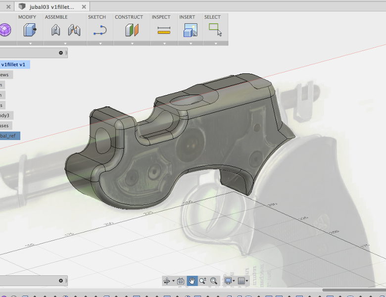 Even Fusion 360. Some of the specific curves and edges I need out of it are far too difficult to
achieve inside the interface. So like pretty much everything else I do, I need to flip the meshes into another application to do some work, then re-import them.
And I just realized it has been several months since I last used that software. They've probably changed the entire thing by now!
At least EagleCAD was a relatively small learning curve, and shouldn't take too long to pick up again...
Meanwhile on Next Generation and later, everyone can use everything that has microcircuits, and there's never even a moment of realizing the docs are all in Klingon or whatever. I think Star Wars gets it a lot closer.
Anyhow.
I've been really sick for a couple of days. And spent it delving into some software I haven't used in far too long. Still learning my way around GIMP, getting better with Inkscape -- and flipping back and forth between those two with great rapidity as I develop the most recent iteration of the Holocron:
And I'm pretty much volunteering the design time, but aside from the vector on the center image, it is all re-purposable for the holocron kits I'll be offering soon at the RPF.
I'm going to be able to offer a fair number of customization options right off the rack, plus option to do new design work as I find time.
Perhaps I'll even some time solve the assembly issue. I've seen some Holocron designs that use a staggered outer edge to hide the way the shell has to be assembled: and those would not need to be sanded and painted.
Anyhow. Figured out an option for the DuckLight battery issue and rigged up a quick test with the prototype; hooked the main circuit to regulated 5v, and plugged the Cree into a separate 4-cell battery pack. It seems to deliver almost the output I achieved with an overall regulated 500ma power supply.
So the scheme now is to add a 3.3v LDO to the PCB. It won't be that wasteful of space; I already need to add the filter capacitors to stabilize the ATtiny.
Pity there's no easy way to cram that in to the current PCB so I could do some proper in-place prototyping. But the boards were only ten bucks.
It's worse than that. I also flip into Poser 6 when I'm rigging a prop, because it is simpler to work in and makes cleaner files.
And for some stuff, DAZstudio is a little easier. At least the camera is superior. But of course the interface is entirely different, in almost every way it can be.
I'm really not looking forward to having to go back into Carrara, but I have some modeling projects in the pipeline that need it. Well, that or Blender...and I'm still having terrible trouble coming to grips with Blender.
Even Fusion 360. Some of the specific curves and edges I need out of it are far too difficult to achieve inside the interface. So like pretty much everything else I do, I need to flip the meshes into another application to do some work, then re-import them.
And I just realized it has been several months since I last used that software. They've probably changed the entire thing by now!
At least EagleCAD was a relatively small learning curve, and shouldn't take too long to pick up again...
Wednesday, February 25, 2015
Knot Working
I still need another job.
The props stuff is keeping me busy, but with only a sound op gig, a small lighting design, and some microphone rentals I'm just barely going to scrape by.
I was messing around with knotwork today -- or more specifically, looking at a lot of stuff about Islamic interlace patterns. The idea was to work up something for my new Jedi Holocron project that takes the "Millennium Falcon Circuitry" pattern of the last one and moves it to more of a repeating decorative pattern...and the religious-art connotations don't hurt, as this is a design for a Jedi Temple.
Not sure why I thought of going in that direction. Maybe memories of the fantastic clockwork facade of the Institut du Monde Arabe in Paris.

The props stuff is keeping me busy, but with only a sound op gig, a small lighting design, and some microphone rentals I'm just barely going to scrape by.
I was messing around with knotwork today -- or more specifically, looking at a lot of stuff about Islamic interlace patterns. The idea was to work up something for my new Jedi Holocron project that takes the "Millennium Falcon Circuitry" pattern of the last one and moves it to more of a repeating decorative pattern...and the religious-art connotations don't hurt, as this is a design for a Jedi Temple.
Not sure why I thought of going in that direction. Maybe memories of the fantastic clockwork facade of the Institut du Monde Arabe in Paris.
So I'm slowly getting used to both Inkscape, and GIMP. Flipping back and forth between them is still...interesting...however, as the key commands are completely different for each. In fact, because Inkscape is running on Xquartz via a Java VM, it remaps command (Mac standard) to control. So something as simple as saving the file takes an extra little bit of concentration.
I still have no idea how to proceed on my power issues with the DuckLight. Seems like I need to live with the idea of larger battery packs if I want the full output power, and add on-board regulators. Which not only adds parts, and footprint, but also means you'd have to change jumpers or something for all those applications where a smaller battery pack is more appropriate.
Hrm. Maybe regulating the ATtiny down to 3.3 volts regardless of battery source makes the most sense. 2xAAA just doesn't light anything but a red LED anyhow, and that's the only set that would be too low for even an LDO. And with a powerful enough regulator, it could supply an XBee, meaning I wouldn't really need a custom daughterboard for those.
One thing I have figured out is what I want to do with those flexible USB lights I picked up for a buck each at Wallgreens. Make little Steampunk-Tiffany task lights out of them. Add a laser-cut acrylic clip/magnet on one end, paint the flexible rod up a nice brass, stick a super blue LED in, and pull some painted/dyed PETG over a hand-carved buck to make a shade.
Now if only I had some sketches I liked for the Raygun. I need to start getting client approval and move into the next design phase!
Monday, February 23, 2015
Jaffa, Cree!
Oh, did I make that joke already?
Internet is back, BTW. It took eight phone calls, an hour of navigating phone "help" menus, three service calls, and over a week...but they finally figured out the modem was dead. You'd think they could ping it and find out, but apparently that particularly modem typically fails in a way that looks like a bad line from both ends. Funny thing is, not even the service techs...two of them, lugging bags of electronic gear from their van...had tools to see if the line actually connected. Only a DSL modem will actually tell you anything, and because of the secure installation procedure it is non-trivial to swap in a test unit.
Only good side to the affair is it gave me the excuse to yank my old desktop and monitor and all the associated cruft and clean up under my work table. It looks much neater and cleaner now, and I can use my scanner without getting a back injury.
Discovered a puzzling problem with the DuckLight board. I noticed it was much brighter running off the 5v regulated supply of a USB port than it was off the 3xAAA battery pack. I thought this might be an amperage issue but a little more experimentation shows it to be voltage related.
 Which is odd. The forward voltage of green LEDs is under 4 volts (3.7 seems typical). The voltage drop of the AMC7135 chip is a mere 0.12 volts. A 3x battery pack should thus be quite sufficient.
Oh, but wait. Calculating with the smaller voltage of nickel-metal hydride (the Sanyo Eneloop rechargeables I use almost exclusively) brings the 3x battery pack to a mere 3.6 volts. Which is far enough into the curve to experience a significant loss of luminosity.
And I had already discovered that on 2xAAA (my designed footprint for the first board) only the red LED lit properly; the green was obviously not getting sufficient voltage.
Well, shucks. The rated output on lithium polymer packs is 3.3 to 3.7 volts -- meaning once again that the most common green LED chemistry won't light at full power. Especially not if I try to run a 3.3 volt bus (to allow direct connection of certain sensors and XBee radios).
So what are the options? Switching to alkaline is not actually a help. Alkalines drop very rapidly in voltage from full charge. In addition, their nominal rating is given in no-load -- unlike NiMH's, which give the nominal voltage rating under design load (due basically to lower internal resistance).
Going significantly over and regulating down to 5 volts would make sense for a more complex project. At a draw of 1 watt or more, though, that's a hefty regulator -- and a lot of heat from wasted wattage. A dual NiMH pack, for instance, regulated to 5 volts, would have to burn off over five WATTS. That's at the peak of what a TO-220 package can handle with a bolt-on external heat sink.
Splitting the difference, a 4x battery pack delivers 4.8 volts nominal -- that's pushing up to 1/4 of the wattage into the regulator, which has to burn it off -- and at full charge can get pretty close to 6 volts. Which fortunately is while out of spec still within the range of what the ATtiny can tolerate! It is also twice the footprint of the board in flat pack and basically annoys me as a form factor even in quad.
(And in case you are wondering, all those Cree flashlights get away with it because "white" LEDs have a lower voltage drop than the common green ones.)
And, bah -- four fully charged eneloops are sufficiently above the voltage spec that the ATtiny shuts down. Which means I would need to include an LDO in order to operate the green LED at full efficiency. Or....regulate just the ATtiny, perhaps at 3.3V for sensor and XBee compatibility...well, according to the literature the AMC7135 really likes to be between 4.5v and 6v. Gets way too hot above that. Like most LDOs, the highest efficiency is when the voltage in is very close to the voltage out.
Well, I still have to finish porting my "blink" code to the new board, and see if there is even possibly enough space left over in program memory to do any of the other tricks I want. One issue from the old Piranha board that the Cree makes a lot more of a problem is the stair-stepping at the low end of the intensity scale. With only 255 steps in my pulse generator, the difference between 1/255 and 2/255 is a little too obvious in LED intensity. So I'm reading up on dithering techniques. (I can't simply increase the PWM bit depth, as I'm running at 8 MHz on internal oscillator and the PWM frequency is already close to critically low).
I also need to do a bake test to make sure the system can handle being ran wide open for a significant interval. I've already noted that 3W is at the low end of theatrical viability. Fortunately, a lot of applications can be served without full RBG -- instead hanging a 3W or even 10W single-color LED on the board and running the current regulators in parallel mode.
Another change that's on the horizon. The old RGBs are slipping in the Chinese suppliers to make room for new cheaper RGBW's. So far no affordable RGBA, but I have my eye on a few affordable RGB-Warm White already. Which is why my board is a four-channel. And why the ATtiny84 -- to give enough extra I/O pins for external sensors/controls. Although I still may end up just going into an ATmega eventually. Especially if I chose one with native USB support. Those are nasty little surface-mount jobbies...but at least they aren't BGA!
I'm also seriously contemplating revamping my headers completely and making the duckNode Trinket compatible. There's a LiPo backpack in that format, for instance. And in the obverse, I could make my XBee shield cross-compatible. The downside is I want to achieve everything possible from the ICSP header alone -- plus a stand-off, which the current iteration omits -- so there is no need to solder header pins to the board in order to program it or even to integrate it with radio link or power regulation. Having pins soldered on is one more thing to work around or to have to remove when cramming the final board into a prop, and the whole purpose of this exercise is to produce the most minimal footprint, lowest parts count and cost to bring full PWM control of 4W RGB/RGBW LEDs.
(So many TLAs there, I'm starting to feel like I work at NASA!)
Internet is back, BTW. It took eight phone calls, an hour of navigating phone "help" menus, three service calls, and over a week...but they finally figured out the modem was dead. You'd think they could ping it and find out, but apparently that particularly modem typically fails in a way that looks like a bad line from both ends. Funny thing is, not even the service techs...two of them, lugging bags of electronic gear from their van...had tools to see if the line actually connected. Only a DSL modem will actually tell you anything, and because of the secure installation procedure it is non-trivial to swap in a test unit.
Only good side to the affair is it gave me the excuse to yank my old desktop and monitor and all the associated cruft and clean up under my work table. It looks much neater and cleaner now, and I can use my scanner without getting a back injury.
Discovered a puzzling problem with the DuckLight board. I noticed it was much brighter running off the 5v regulated supply of a USB port than it was off the 3xAAA battery pack. I thought this might be an amperage issue but a little more experimentation shows it to be voltage related.
Which is odd. The forward voltage of green LEDs is under 4 volts (3.7 seems typical). The voltage drop of the AMC7135 chip is a mere 0.12 volts. A 3x battery pack should thus be quite sufficient.Oh, but wait. Calculating with the smaller voltage of nickel-metal hydride (the Sanyo Eneloop rechargeables I use almost exclusively) brings the 3x battery pack to a mere 3.6 volts. Which is far enough into the curve to experience a significant loss of luminosity.
And I had already discovered that on 2xAAA (my designed footprint for the first board) only the red LED lit properly; the green was obviously not getting sufficient voltage.
Well, shucks. The rated output on lithium polymer packs is 3.3 to 3.7 volts -- meaning once again that the most common green LED chemistry won't light at full power. Especially not if I try to run a 3.3 volt bus (to allow direct connection of certain sensors and XBee radios).
So what are the options? Switching to alkaline is not actually a help. Alkalines drop very rapidly in voltage from full charge. In addition, their nominal rating is given in no-load -- unlike NiMH's, which give the nominal voltage rating under design load (due basically to lower internal resistance).
Going significantly over and regulating down to 5 volts would make sense for a more complex project. At a draw of 1 watt or more, though, that's a hefty regulator -- and a lot of heat from wasted wattage. A dual NiMH pack, for instance, regulated to 5 volts, would have to burn off over five WATTS. That's at the peak of what a TO-220 package can handle with a bolt-on external heat sink.
Splitting the difference, a 4x battery pack delivers 4.8 volts nominal -- that's pushing up to 1/4 of the wattage into the regulator, which has to burn it off -- and at full charge can get pretty close to 6 volts. Which fortunately is while out of spec still within the range of what the ATtiny can tolerate! It is also twice the footprint of the board in flat pack and basically annoys me as a form factor even in quad.
(And in case you are wondering, all those Cree flashlights get away with it because "white" LEDs have a lower voltage drop than the common green ones.)
And, bah -- four fully charged eneloops are sufficiently above the voltage spec that the ATtiny shuts down. Which means I would need to include an LDO in order to operate the green LED at full efficiency. Or....regulate just the ATtiny, perhaps at 3.3V for sensor and XBee compatibility...well, according to the literature the AMC7135 really likes to be between 4.5v and 6v. Gets way too hot above that. Like most LDOs, the highest efficiency is when the voltage in is very close to the voltage out.
Well, I still have to finish porting my "blink" code to the new board, and see if there is even possibly enough space left over in program memory to do any of the other tricks I want. One issue from the old Piranha board that the Cree makes a lot more of a problem is the stair-stepping at the low end of the intensity scale. With only 255 steps in my pulse generator, the difference between 1/255 and 2/255 is a little too obvious in LED intensity. So I'm reading up on dithering techniques. (I can't simply increase the PWM bit depth, as I'm running at 8 MHz on internal oscillator and the PWM frequency is already close to critically low).
I also need to do a bake test to make sure the system can handle being ran wide open for a significant interval. I've already noted that 3W is at the low end of theatrical viability. Fortunately, a lot of applications can be served without full RBG -- instead hanging a 3W or even 10W single-color LED on the board and running the current regulators in parallel mode.
Another change that's on the horizon. The old RGBs are slipping in the Chinese suppliers to make room for new cheaper RGBW's. So far no affordable RGBA, but I have my eye on a few affordable RGB-Warm White already. Which is why my board is a four-channel. And why the ATtiny84 -- to give enough extra I/O pins for external sensors/controls. Although I still may end up just going into an ATmega eventually. Especially if I chose one with native USB support. Those are nasty little surface-mount jobbies...but at least they aren't BGA!
I'm also seriously contemplating revamping my headers completely and making the duckNode Trinket compatible. There's a LiPo backpack in that format, for instance. And in the obverse, I could make my XBee shield cross-compatible. The downside is I want to achieve everything possible from the ICSP header alone -- plus a stand-off, which the current iteration omits -- so there is no need to solder header pins to the board in order to program it or even to integrate it with radio link or power regulation. Having pins soldered on is one more thing to work around or to have to remove when cramming the final board into a prop, and the whole purpose of this exercise is to produce the most minimal footprint, lowest parts count and cost to bring full PWM control of 4W RGB/RGBW LEDs.
(So many TLAs there, I'm starting to feel like I work at NASA!)
Saturday, February 21, 2015
Dead Head
Ran out to the Rose Garden to take some pictures, but the roses are very much not in bloom at the moment. Whoops. We stayed until it got cold and dark anyhow. Yes; a sheet of foam-core works very well at providing a nice diffuse fill light....when there's enough direct light falling on it.
Ran the prototype current-controlled DuckLight for about four hours without any sign of overheating or the LED being overdriven. Next I think is an acid test; put a minimal heatsink on the LED and run it full-out for an hour or two. Those AMC7135's are totally the ticket!
The Holocron enquiry got one response. I'm working up a new Holocron design for a Jedi Academy now. Have in mind a combination I think will work, but haven't actually gotten into Illustrator (rather, InkScape) yet.
HP is now on my "nice" list. The scanner software I was using demanded I upgrade, told me upgrades were no longer free, and threw up its hands when presented with a 64-bit OS and what was apparently a 32-bit scanner driver. "Go call HP and see if they have any drivers," was all the software could offer. So I did, and HP had...a completely free and compatible scanner package I'm using now instead.
 And I finally got off one sketch of the "art gun" direction for the raygun commission that I actually like.
Sure, I have to work on the proportions some more, and I have no idea how to machine some of it, but it in my mind finally achieves that blend of looking like the shape came out of art school but the details and machining are tight and quality.
It may not be quite period-looking enough, though. (Especially since to my mind the perfect combination would be stained and varnished wood furniture, and aluminium parts anodized in a pale green.)
So continue the sketches. Eventually I'll stumble upon a few that are decent enough to show to the client.
Ran the prototype current-controlled DuckLight for about four hours without any sign of overheating or the LED being overdriven. Next I think is an acid test; put a minimal heatsink on the LED and run it full-out for an hour or two. Those AMC7135's are totally the ticket!
The Holocron enquiry got one response. I'm working up a new Holocron design for a Jedi Academy now. Have in mind a combination I think will work, but haven't actually gotten into Illustrator (rather, InkScape) yet.
HP is now on my "nice" list. The scanner software I was using demanded I upgrade, told me upgrades were no longer free, and threw up its hands when presented with a 64-bit OS and what was apparently a 32-bit scanner driver. "Go call HP and see if they have any drivers," was all the software could offer. So I did, and HP had...a completely free and compatible scanner package I'm using now instead.
And I finally got off one sketch of the "art gun" direction for the raygun commission that I actually like.Sure, I have to work on the proportions some more, and I have no idea how to machine some of it, but it in my mind finally achieves that blend of looking like the shape came out of art school but the details and machining are tight and quality.
It may not be quite period-looking enough, though. (Especially since to my mind the perfect combination would be stained and varnished wood furniture, and aluminium parts anodized in a pale green.)
So continue the sketches. Eventually I'll stumble upon a few that are decent enough to show to the client.
Nile Project
Started the school tour (9 AM performances!) That show is open now, so another plate is quietly spinning...
 Also shipped the next eight M40 grenades. That makes 35 of the things I've sold now. The new
processes didn't work quite as well as I wanted, and I still need to purchase some new tooling, but it got down to under three hours of labor each -- less than two for the machining.
 Someone asked for the files on the Holocron and I've gone ahead and indicated I will produce a kit if requested. Perhaps I should start an INT thread at the RPF as well?
That makes the prop priority the Raygun. Although the final ship deadline is a ways off, it would be better business if I got it done a lot sooner -- soon enough for other "space tiki" fanatics to decide they want one, too.
 And the AMC7135's I've been waiting on finally showed up. I enquired at a couple local stores for solder paste and checked prices at some online suppliers, but I was able to solder up the first SMD with a regular iron and some nice Kester silver solder I picked up at Al Lasher's Electronics.
There's a few mistakes on the PCB. I expected that. The trimpot sits too close to the ICSP header, and I'd managed to mis-identify the correct external clock pin for programming. Well, that's what jumpers are for.
The main purpose of the board was, after all, to test the AMC7135's. And after I fixed my screw-up with the ICSP wiring, it came through. I had to stop the full-power test because the LED needs a heat-sink if it is to be operated all out, but the AMC7135's appear to be limiting the current quite nicely, AND are responding correctly to the ATtiny. After a couple of hitches I have software PWM running. Seems a wee bit unstable -- so when I make the next version it will have a filter cap across the power lines of the DIP, and perhaps something on the RESET pin as well.
But before I get deep into revamping the PCB, I have software to write.

processes didn't work quite as well as I wanted, and I still need to purchase some new tooling, but it got down to under three hours of labor each -- less than two for the machining.
That makes the prop priority the Raygun. Although the final ship deadline is a ways off, it would be better business if I got it done a lot sooner -- soon enough for other "space tiki" fanatics to decide they want one, too.
There's a few mistakes on the PCB. I expected that. The trimpot sits too close to the ICSP header, and I'd managed to mis-identify the correct external clock pin for programming. Well, that's what jumpers are for.
The main purpose of the board was, after all, to test the AMC7135's. And after I fixed my screw-up with the ICSP wiring, it came through. I had to stop the full-power test because the LED needs a heat-sink if it is to be operated all out, but the AMC7135's appear to be limiting the current quite nicely, AND are responding correctly to the ATtiny. After a couple of hitches I have software PWM running. Seems a wee bit unstable -- so when I make the next version it will have a filter cap across the power lines of the DIP, and perhaps something on the RESET pin as well.
But before I get deep into revamping the PCB, I have software to write.
Tuesday, February 3, 2015
Begosh
The first PCBs arrived from OSH Park:

I partially populated one (nothing's soldered yet) to check if the footprints I designed in Eagle matched the parts I ordered from Digikey. So far, so good. Except that the key part -- the current limiters -- are coming via "International Airmail" from Fasttech and there is no tracking available.
Assuming the AMC7135's work -- which is really what this board is intended to test -- I already have a few ideas towards the next iteration. Probably drop the breadboard spacing for the outer pins, go to a lower profile trim pot and switch to SMT for the LEDs as well (so I can add more blinkenlights -- serial data, the traditional "pin 13 LED" of Arduino compatibles, and of course keep the power light.)
And I haven't quite figured out the best format for the XBee backpack (plus I keep searching for more budget-conscious alternatives to the XBee).
Here's what the board replaces:

That's the quick-and-dirty vero board version I made for the radio light. Only two channels on this one, as I was mixing red and green LED for a sort of amber light. That toggle you see is hot-glued to the side of a AAA battery pack. At least this iteration had the ICSP header, making it a little less annoying to tweak the software.
It was sitting inside this prop:

(Dress rehearsal photograph made by Anna Kaminska for Actor's Ensemble). Also taken before I replaced the ailing previous circuit with one that could reliably generate a decent amber.
So, sure, the new circuit is smaller, and as fast as I am with the vero board (or, rather, the somewhat expensive but totally worth it "Perma-Proto" stripboard from Adafruit) having already wired and partially programmed versions should make it a lot easier to add it to productions.
But more than that -- with wiring and programming already in place and basic options available just by turning a knob and hitting a button, this should be useable by people who don't have the time and experience to learn all this stuff themselves.
I partially populated one (nothing's soldered yet) to check if the footprints I designed in Eagle matched the parts I ordered from Digikey. So far, so good. Except that the key part -- the current limiters -- are coming via "International Airmail" from Fasttech and there is no tracking available.
Assuming the AMC7135's work -- which is really what this board is intended to test -- I already have a few ideas towards the next iteration. Probably drop the breadboard spacing for the outer pins, go to a lower profile trim pot and switch to SMT for the LEDs as well (so I can add more blinkenlights -- serial data, the traditional "pin 13 LED" of Arduino compatibles, and of course keep the power light.)
And I haven't quite figured out the best format for the XBee backpack (plus I keep searching for more budget-conscious alternatives to the XBee).
Here's what the board replaces:
That's the quick-and-dirty vero board version I made for the radio light. Only two channels on this one, as I was mixing red and green LED for a sort of amber light. That toggle you see is hot-glued to the side of a AAA battery pack. At least this iteration had the ICSP header, making it a little less annoying to tweak the software.
It was sitting inside this prop:
(Dress rehearsal photograph made by Anna Kaminska for Actor's Ensemble). Also taken before I replaced the ailing previous circuit with one that could reliably generate a decent amber.
So, sure, the new circuit is smaller, and as fast as I am with the vero board (or, rather, the somewhat expensive but totally worth it "Perma-Proto" stripboard from Adafruit) having already wired and partially programmed versions should make it a lot easier to add it to productions.
But more than that -- with wiring and programming already in place and basic options available just by turning a knob and hitting a button, this should be useable by people who don't have the time and experience to learn all this stuff themselves.
Saturday, January 24, 2015
Laser Rifles and Dying Fairies
Not, not "Wizards, The Musical" (which one day, in some other life, I would love to have a part in producing).
I took a short job in The City -- for low enough pay a third of it is going to pay BART fare -- and once again an application came up for a DuckLight. Which is currently in the form of a PCB being manufactured in China. That is, the prototype board is. I figure there's about a 50% chance the first board will actually work correctly.
Once again, I would have saved a lot of time if I could have just reached into my kit and pulled one out. But also, once again, I hadn't imagined anything like this application until it came long.
Tinkerbell. There's a spot in the musical where Tink needs to go into her little house and stay there for a while. I had already planned for one of the default animations on the DuckLight to be a flicker or shimmer, but I didn't even know why I wanted that. Now I do. Dial up a nice Tinkerbell green and the effect is half-way there.
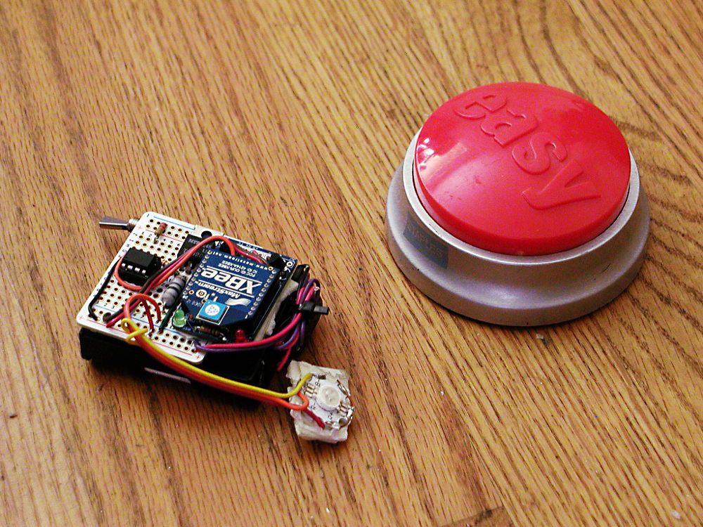 Only half-way, because this production is children's theater. No onstage actor is going to be able to hit a switch. So it needs the next element, the next board up in my Eagle-and-fab list; the XBee backpack.
Well, I did pull a morning of very swift soldering, and set up a single-channel AVR-controlled Cree and attached an XBee to it in line-passing mode. There was some strangeness going on with lines floating or automatically resetting or something but by adding a double-click detect I finally got it reliable enough to use it over the closing performances.
 Otherwise Tink is being played by a laser. Which still makes me uncomfortable, even though I opened up the beam focus until the power is much spread out. To hit his targets the follow-spot operator went and attached the laser to three-foot long stick of wood that he braces against his shoulder. Naturally I took to calling this contraption his "Laser Rifle."
Being one of the bargain bulk optical goods from the industrious young engineers in Shanghai, this particularly laser diode is not stable enough, cooled enough, or otherwise suitable for leaving on for longer than a few seconds at a time. As a stop-gap, I put an AVR-powered switch on it that randomly blinks it off for half a second or so every few seconds. That seems to help, but I'm betting I'll still be out a laser diode before the show closes.
The blinking looks quite natural and Tink-like. Particularly tonight's performance. Right after Wendy said, "Wouldn't you say so, Tinkerbell?" the light blinked several times in quick succession as if Tink was making an acerbic reply.
 Here's the full circuit in better light, by the way:
The 8-pin dip is the ATtiny85 running the random blink routine. The Tip-120 switches laser power, with a blinkenlight wired in parallel as a status monitor. Another one monitors the battery connection, which is switched on and off by the momentary button. That's the nice thing about these AVR's; supply power, and it boots up softly in milliseconds and starts running the program loop.
This was all in all another informative show. I need that serial Xbee connection for reliable triggering, and this makes twice now that 3 watts of RGB was a little marginal. Unfortunately the jump to 10 watts of LED power brings in a whole new level of current regulator and thermal management complexity.
I took a short job in The City -- for low enough pay a third of it is going to pay BART fare -- and once again an application came up for a DuckLight. Which is currently in the form of a PCB being manufactured in China. That is, the prototype board is. I figure there's about a 50% chance the first board will actually work correctly.
Once again, I would have saved a lot of time if I could have just reached into my kit and pulled one out. But also, once again, I hadn't imagined anything like this application until it came long.
Tinkerbell. There's a spot in the musical where Tink needs to go into her little house and stay there for a while. I had already planned for one of the default animations on the DuckLight to be a flicker or shimmer, but I didn't even know why I wanted that. Now I do. Dial up a nice Tinkerbell green and the effect is half-way there.
Only half-way, because this production is children's theater. No onstage actor is going to be able to hit a switch. So it needs the next element, the next board up in my Eagle-and-fab list; the XBee backpack.Well, I did pull a morning of very swift soldering, and set up a single-channel AVR-controlled Cree and attached an XBee to it in line-passing mode. There was some strangeness going on with lines floating or automatically resetting or something but by adding a double-click detect I finally got it reliable enough to use it over the closing performances.
Otherwise Tink is being played by a laser. Which still makes me uncomfortable, even though I opened up the beam focus until the power is much spread out. To hit his targets the follow-spot operator went and attached the laser to three-foot long stick of wood that he braces against his shoulder. Naturally I took to calling this contraption his "Laser Rifle."Being one of the bargain bulk optical goods from the industrious young engineers in Shanghai, this particularly laser diode is not stable enough, cooled enough, or otherwise suitable for leaving on for longer than a few seconds at a time. As a stop-gap, I put an AVR-powered switch on it that randomly blinks it off for half a second or so every few seconds. That seems to help, but I'm betting I'll still be out a laser diode before the show closes.
The blinking looks quite natural and Tink-like. Particularly tonight's performance. Right after Wendy said, "Wouldn't you say so, Tinkerbell?" the light blinked several times in quick succession as if Tink was making an acerbic reply.
The 8-pin dip is the ATtiny85 running the random blink routine. The Tip-120 switches laser power, with a blinkenlight wired in parallel as a status monitor. Another one monitors the battery connection, which is switched on and off by the momentary button. That's the nice thing about these AVR's; supply power, and it boots up softly in milliseconds and starts running the program loop.
This was all in all another informative show. I need that serial Xbee connection for reliable triggering, and this makes twice now that 3 watts of RGB was a little marginal. Unfortunately the jump to 10 watts of LED power brings in a whole new level of current regulator and thermal management complexity.
Wednesday, January 21, 2015
Lot of work for so little pay
Inventoried stock and ordered the remainder for the next round of Stage Lights. Also reminded the purchaser I was barely covering expenses on them and soon I'd have to charge more.
Struggled some more with parts libraries in Eagle. The software has been through some changes recently and some of the more common suggestions found online no longer work. But I got it together and sent off an order for the first try at a board to OSHpark.
Inventoried my Aliens Grenade supplies, made up an order for new material, and sat down with a bunch of snapcaps and shotshells to check dimensions. Watching snippets of the movie again. I am increasingly of two minds about my design.
There's almost a fanon when you get to stuff like this; how it may have actually looked in the movie, and how prop-makers are tending to make them look these days. Aliens has a bit of that; the original Pulse Rifles were painted brown, but they read olive drab under the lighting of the movie. So which is more accurate? The actual color of the prop, or the color the prop appeared in the movie?
In the case of the grenades, there are sadly few high-resolution images, and few documented screen-used with decent images available. So one could make in a sense two different arguments; one for what the prop-makers probably provided, and what is therefor most accurate to a world in which a film was made about a bunch of space marines. And one for what is just at the verge of visibility, possibly hidden in blur and lighting effects; the world in which Weyland-Utani managed to get a bunch of them killed on a remote colony world.
In re the outer world, I have more than strong suspicions that the grooves were made with a thread-cutting tool, and are probably v-shaped. The spring-loaded trigger, of which there were unlikely more than one or two to begin with, was top-loaded. The nose is a simple chamfer and there is no "nose ring." And the cap was off-white, painted in various colors (seemingly red, dark blue, a rather washed-out green, and perhaps one or two in yellow), with a strip of teflon plumbing tape or a hand-painted white line. Oh, yes; and I have reason to believe there was a fairly large cut-out in the bottom, with the primer sticking out like a very short lamp post.
In the inner, diagetic world, these have more distinction in their markings. My head canon is that originally the caps were shaped differently to reflect the various loads, and as well some of the bodies are distinctive. Manuals and other materials were released on the basis of those models, but in the usual business of military contract bidding they ended up sharing molds and the items issued at the time of the film had lost some of those distinctions. And furthermore, GI's of any generation are playful, and once they found out the protective caps were interchangeable, would start putting them on randomly in whatever suited their own color/fashion sense.
And at some nearly orthogonal angle to either of these directions of approach, are the prop-maker's aesthetics. The major reason to keep those in mind is because one cosplayer may have props from more than one supplier. And more than one cosplayer may appear in the same picture. So if everyone is making their M51A's a bright baby blue, it makes a certain sense to follow suit.
The major elements found in fan-made grenades are however varied. Some have the tree-stump firing pins, others look more shotgun-like. Some have chamfered noses, some have rounded noses. However, almost all have squared-off grooves.
Which leaves me basically floundering between two untenables; follow the best guess of the best information and end up with a result that doesn't meet expectation: or do what fulfills my personal aesthetic judgment and is somewhat defensible both diagetically and historically -- but only somewhat, as the design combines elements I can not be sure of with elements I am reasonably certain are wrong.
Oh, yes. And I also got another reweld mentioned at me. A ZB-30, which from a brief look appears insane.
Struggled some more with parts libraries in Eagle. The software has been through some changes recently and some of the more common suggestions found online no longer work. But I got it together and sent off an order for the first try at a board to OSHpark.
Inventoried my Aliens Grenade supplies, made up an order for new material, and sat down with a bunch of snapcaps and shotshells to check dimensions. Watching snippets of the movie again. I am increasingly of two minds about my design.
There's almost a fanon when you get to stuff like this; how it may have actually looked in the movie, and how prop-makers are tending to make them look these days. Aliens has a bit of that; the original Pulse Rifles were painted brown, but they read olive drab under the lighting of the movie. So which is more accurate? The actual color of the prop, or the color the prop appeared in the movie?
In the case of the grenades, there are sadly few high-resolution images, and few documented screen-used with decent images available. So one could make in a sense two different arguments; one for what the prop-makers probably provided, and what is therefor most accurate to a world in which a film was made about a bunch of space marines. And one for what is just at the verge of visibility, possibly hidden in blur and lighting effects; the world in which Weyland-Utani managed to get a bunch of them killed on a remote colony world.
In re the outer world, I have more than strong suspicions that the grooves were made with a thread-cutting tool, and are probably v-shaped. The spring-loaded trigger, of which there were unlikely more than one or two to begin with, was top-loaded. The nose is a simple chamfer and there is no "nose ring." And the cap was off-white, painted in various colors (seemingly red, dark blue, a rather washed-out green, and perhaps one or two in yellow), with a strip of teflon plumbing tape or a hand-painted white line. Oh, yes; and I have reason to believe there was a fairly large cut-out in the bottom, with the primer sticking out like a very short lamp post.
In the inner, diagetic world, these have more distinction in their markings. My head canon is that originally the caps were shaped differently to reflect the various loads, and as well some of the bodies are distinctive. Manuals and other materials were released on the basis of those models, but in the usual business of military contract bidding they ended up sharing molds and the items issued at the time of the film had lost some of those distinctions. And furthermore, GI's of any generation are playful, and once they found out the protective caps were interchangeable, would start putting them on randomly in whatever suited their own color/fashion sense.
And at some nearly orthogonal angle to either of these directions of approach, are the prop-maker's aesthetics. The major reason to keep those in mind is because one cosplayer may have props from more than one supplier. And more than one cosplayer may appear in the same picture. So if everyone is making their M51A's a bright baby blue, it makes a certain sense to follow suit.
The major elements found in fan-made grenades are however varied. Some have the tree-stump firing pins, others look more shotgun-like. Some have chamfered noses, some have rounded noses. However, almost all have squared-off grooves.
Which leaves me basically floundering between two untenables; follow the best guess of the best information and end up with a result that doesn't meet expectation: or do what fulfills my personal aesthetic judgment and is somewhat defensible both diagetically and historically -- but only somewhat, as the design combines elements I can not be sure of with elements I am reasonably certain are wrong.
Oh, yes. And I also got another reweld mentioned at me. A ZB-30, which from a brief look appears insane.
Monday, January 19, 2015
CAD Woes
Trying to get the PCB ordered on my prototype "DuckLight." The first Eagle layout looked pretty good, but it seemed possible to shrink the board's footprint until it was only 2xAAA wide. Which you can run on, but it runs the LEDs a little cold.
Anyhow, I shrunk the layout and ran traces by hand. I was also conscious of the potential difficulties in soldering SMDs so I made a point of holding the traces far outside of the pads of those parts. So that took a couple of evenings. But got it down to one via (well, I also ended up omitting a duplicate VCC on the second header. It would have required multiple vias in order to get the connection.)
I used a part with internal connections (a tactile switch) as a jumped in one spot, and Eagle kept flagging it. So I went to the forums for the first time with a question. And it turns out not only have lots of people asked about this, there is no current solution.
But then I went to order the parts to make sure the ones in the CAD were actually available stock. I'd used the SparkFun Eagle library in several places, and you'd think this would be a shoe-in, right? But no. The part in their library doesn't actually have an analog in their store.
They did have something in their store that I could modify the package to, however. And after a bit of struggling re-routing around the new (and larger) dimensions, I had confirmation of available parts.
The final DRCs, and Eagle starts throwing up mask errors. Turns out that, yes once again, many of the library parts I was using have a silkscreen that goes over the copper traces. Which can be a problem at smaller fab houses that don't have the software to fix this on the fly. So back once again to the package designs, now to edit all the silkscreens.
Nice of various people to make libraries available to everyone, but really, could they adhere a little closer to reality?
Anyhow, I shrunk the layout and ran traces by hand. I was also conscious of the potential difficulties in soldering SMDs so I made a point of holding the traces far outside of the pads of those parts. So that took a couple of evenings. But got it down to one via (well, I also ended up omitting a duplicate VCC on the second header. It would have required multiple vias in order to get the connection.)
I used a part with internal connections (a tactile switch) as a jumped in one spot, and Eagle kept flagging it. So I went to the forums for the first time with a question. And it turns out not only have lots of people asked about this, there is no current solution.
But then I went to order the parts to make sure the ones in the CAD were actually available stock. I'd used the SparkFun Eagle library in several places, and you'd think this would be a shoe-in, right? But no. The part in their library doesn't actually have an analog in their store.
They did have something in their store that I could modify the package to, however. And after a bit of struggling re-routing around the new (and larger) dimensions, I had confirmation of available parts.
The final DRCs, and Eagle starts throwing up mask errors. Turns out that, yes once again, many of the library parts I was using have a silkscreen that goes over the copper traces. Which can be a problem at smaller fab houses that don't have the software to fix this on the fly. So back once again to the package designs, now to edit all the silkscreens.
Nice of various people to make libraries available to everyone, but really, could they adhere a little closer to reality?
Tuesday, January 13, 2015
Wanna Flyyy with the Eagle, Make PCs...
...Try out the Eagle 'cause the non-profit version's free!

After reading that Fritzing was not recommended for SMT components, I loaded up EagleCAD again to give it a proper try this time. And I like it. Fritzing is still low-key, friendly, and amusing, and the graphics for the Breadboard mode are excellent for things like Instructables and also for working out gross component arrangement. But Eagle is serious CAD, with lots of good tools.
The organization of the parts libraries still confuses me, but I was able to at least create the custom parts I needed and place them in a directory where I could find them again. Above is the first attempt by the auto-router -- it looks surprisingly good, but I suspect I'll be hand-routing some traces.
Now that I've seen it is rout-able, I can work on the footprint a little more. I'm hoping to get it to the same width as a 2-pack of AAA batteries (even though my optimum design is now 3xAAA -- and that is also the version which is getting tested in a currently-running show).
The SOT-89 packages for the AMC7135's are the only SMDs on the board. I may turn some of the other discretes and blinkenlights into SMT components, but the big footprint hog right now is the I/O pins. I have them spaced right now for breadboard compatibility, but it may make more sense to move and condense them.
I'm also tempted to run off a 3-channel version with an ATtiny85 CPU. Smaller, sure, but also less parts to get wrong on my first venture into getting a board fabbed, and soldering my first SMDs.
After reading that Fritzing was not recommended for SMT components, I loaded up EagleCAD again to give it a proper try this time. And I like it. Fritzing is still low-key, friendly, and amusing, and the graphics for the Breadboard mode are excellent for things like Instructables and also for working out gross component arrangement. But Eagle is serious CAD, with lots of good tools.
The organization of the parts libraries still confuses me, but I was able to at least create the custom parts I needed and place them in a directory where I could find them again. Above is the first attempt by the auto-router -- it looks surprisingly good, but I suspect I'll be hand-routing some traces.
Now that I've seen it is rout-able, I can work on the footprint a little more. I'm hoping to get it to the same width as a 2-pack of AAA batteries (even though my optimum design is now 3xAAA -- and that is also the version which is getting tested in a currently-running show).
The SOT-89 packages for the AMC7135's are the only SMDs on the board. I may turn some of the other discretes and blinkenlights into SMT components, but the big footprint hog right now is the I/O pins. I have them spaced right now for breadboard compatibility, but it may make more sense to move and condense them.
I'm also tempted to run off a 3-channel version with an ATtiny85 CPU. Smaller, sure, but also less parts to get wrong on my first venture into getting a board fabbed, and soldering my first SMDs.
Subscribe to:
Posts (Atom)