There has been a push since at least the Industrial Revolution to offload the rote work -- the repetitive, mindless tasks -- onto machinery. The Maker revolution dotes on this, and my personal props work has paralleled; moving to technologies that let me copy and paste details instead of sculpting them individually, using mills and other power tools to achieve desired surfaces instead of hand-smoothing them, etc.
The downside, though, of getting rid of as much of the mindless drudge work as possible, is you don't have mindless drudge work to do when you are tired, sick, it is hot and you just got off a long day's work, you only have an hour before you need to go off and do something else, etc.
I'm looking at a big task list for the Holocron orders right now. Sure, there's some sanding and patching, and some soldering. Those are mindless; I sanded the last one over a couple evenings while watching YouTube.
But before I can even tear into the stack of orders I need to fix a couple remaining issues. I need to do the next round of PCB corrections in Eagle CAD. I need to edit the new solution to the USB jack into the laser SVG's. I need to dial in the sensitivity on the sensor and write a couple of new functions into the software.
None of this is stuff I can do when sleepy or when my head is fuzzy or when I'm distracted. None of them can I do without several consecutive hours to look through the change orders, re-familiarize myself with the parts/functions/software/layers etc., and still have the time to take careful caliper measurements and run tests and otherwise make sure the work is being done accurately. I can't throw any of this at the wall in hopes it will stick. It requires a free day (or at least a free afternoon) with health and no major distractions.
I can't even make up the rest of the stack of version 1.0 PCBs. Because before I can get to the relatively mindless rote of soldering in the discrete components I have to delicately place the surface mount and run a reflow oven cycle. That takes the kind of steady hand that does not come after the fourth cup of coffee and in any case requires a free hour or more for setup and cleanup.
The line continues to move, of course. Code crunching is increasingly moving to automation now. PCB is automated (if you like the results, which I don't). But of course that merely amplifies the problem. Because then the work that needs to be done so the project can progress is the intense concentration of original insight and artistic thought.
And, yeah, you can (and I've been forced to, on more than one theatrical design contract) reach into your bucket of trite old ideas, recycled ideas, and stolen ideas. And the people around you will still coo and aw about how creative you are.
But it isn't as good and it really doesn't feel right. Every single lighting design I've done for theater has involved me spending at least two hours doing nothing but sitting in a chair in the auditorium staring at the set. My average is a week of back-burner, of thinking off and on about the show, making scribbles, re-reading the script, etc., until the idea finally comes.
Fortunately, that kind of necessary percolation does seem to be entirely compatible with being tired, sick, busy, hot, whatever. It just needs the world to spin a few times before the ideas are ready to take full form.
Showing posts with label CAD. Show all posts
Showing posts with label CAD. Show all posts
Thursday, November 10, 2016


Friday, October 7, 2016
I saw a pocket watch
That pretty much sums up the current direction of Fusion360.
Fusion is a great ap, and the new pricing schedule is actually affordable. But it does have it's peccadilloes. Chief among them being that it is being revised and revamped so frequently there are no current manuals or online help sources or other instructions that actually apply to the real program (they all reference buttons, functions, or entire modes of employ that got taken out several program versions ago).
This updating is, also, forced. On at least three occasions I've had a deadline -- I had to finish a model and I only had a few hours to do so -- but Fusion360 (unlike every other, intelligent, application) makes updates mandatory. Stop work and wait for their extremely slow server (two hours wait to download the latest update, not infrequently). No, you can't work in the background. No, you can't put it off. No, you can't even "fool" it by turning off wifi -- because Fusion360 is so damned cloud-minded all of your data files become inaccessible when you go offline. No matter where you try to force their storage.
So the latest update pushed through (along with the ominous warning that the next update will require an OS update, forcing me to use an OS with known and serious flaws), and it took even longer to start working. The side panel where all of my files are accessed stayed blank for a frighteningly long time, and when I hovered the mouse over it.......
....I got a watch face.
Anyone who knows anything about the Mac OS flees in terror at this point. You should NEVER be that deep into legacy cruft where you see the watch face. It basically means some programmer screwed up bad.
Fusion is a great ap, and the new pricing schedule is actually affordable. But it does have it's peccadilloes. Chief among them being that it is being revised and revamped so frequently there are no current manuals or online help sources or other instructions that actually apply to the real program (they all reference buttons, functions, or entire modes of employ that got taken out several program versions ago).
This updating is, also, forced. On at least three occasions I've had a deadline -- I had to finish a model and I only had a few hours to do so -- but Fusion360 (unlike every other, intelligent, application) makes updates mandatory. Stop work and wait for their extremely slow server (two hours wait to download the latest update, not infrequently). No, you can't work in the background. No, you can't put it off. No, you can't even "fool" it by turning off wifi -- because Fusion360 is so damned cloud-minded all of your data files become inaccessible when you go offline. No matter where you try to force their storage.
So the latest update pushed through (along with the ominous warning that the next update will require an OS update, forcing me to use an OS with known and serious flaws), and it took even longer to start working. The side panel where all of my files are accessed stayed blank for a frighteningly long time, and when I hovered the mouse over it.......
....I got a watch face.
Anyone who knows anything about the Mac OS flees in terror at this point. You should NEVER be that deep into legacy cruft where you see the watch face. It basically means some programmer screwed up bad.
Sunday, September 25, 2016
The light went out!
Alternative title (for those who don't remember Ralph Bashki's Wizards); "Hey! Who turned out the lights!" (One of the freakiest Doctor Who monsters ever!)
I tested the load sharing and charge circuit on my new board. The battery I had been using for testing was pretty badly drained and after waiting two hours it was a relief to see the "charge" light finally go out. Means the schotkey and MOSFET are doing their jobs correctly. Next up is install it in a holocron for a lighting test. Then write some quick-and-dirty code to test the user option buttons.
Taking a step back, this is a big change in how I do electronics. I was just window-shopping at Adafruit and I realized I don't see myself needing any protoboard soon. Or even a lot of hookup wire. I've pretty much moved over to PCBs.

To recap, this is the process of the Holocron circuit I'm testing now;
1) Drew up the schematic in EAGLE
2) Ordered parts, mostly from Digikey
3) Drafted the board in EAGLE
4) Sent the EAGLE files out to OSHpark, a board making company.
5) When all the mail had arrived, stuck the smaller parts on the board with a syringe of paste and then put the board into my T-962 to solder them all at one go.
6) After the board cooled, hand-soldered larger components like the USB jacks.
7) Attached my Adafruit USBtinyISP to the new board's header, and flashed the on-board CPU with the software I'd written in the Arduino IDE.
8) Test and install
The first disjunct from how I did things as a teen is although I still have a big parts box, I don't use it unless I've made a mistake or need to test something or are too impatient. For the most part, I spec out the exact components I need and find them through the parametric sorting system at Digikey.
Digikey is very friendly towards small orders, and has a huge catalog. What makes it navigable is their parametric system; the usual method is to drill down, specifying the most important values first and winnowing down the choices.
The next big change is going to printed circuit boards. There are a number of fab houses now that will do small prototype runs for cheap. So I do a lot less of assembling components on protoboard (although that still has its place). PCBs allow me to make a denser, more compact board, they offer much higher reliability, they are faster, and lastly, they are the only practical way to include surface-mount components.

EAGLE is the key tool here. There are other programs to draft PCBs. EAGLE has a hobby version that is essentially full-function (just restricted in board size and layer count). It also has a schematic editor, and the nifty thing is, board and schematic are automatically linked. So the software will ensure you route your copper traces to make exactly the same connections as are shown in the schematic.
There are software tools out there to simulate the circuit itself. I haven't used those yet. Schematic is helpful enough. The big trick with EAGLE is parts libraries. There are many libraries contributed by users (the big hobby vendors like Spark Fun and Adafruit have libraries for most of the parts they sell) but I'm afraid not all the footprints are trustworthy. So the trick with EAGLE is to slowly build up your own unique library of trusted parts, parts you have personally verified on a PCB you have made. Fortunately, the EAGLE editor is odd, but useable; I've several personally created parts that have now been tested in production.

It is quite possible to hand-solder surface mount (some crazy people even hand-solder the seemingly impossible, like BGA components). Faster, neater, and more electrically sound results come from reflow soldering. Basically you put a specially formulated paste of microspheres of solder in a flux base on the board, plop the components on top, and then carefully bring it to a calculated temperature over a carefully timed interval so the solder melts, flows, and then hardens correctly.
The software-controlled infrared heat lamp of my T-962 reflow oven does this quite nicely (many people have improved their T-962's, many others have made their own out of toaster ovens and microcontrollers).

And then I'm in the Arduino infrastructure. Arduino is basically a wrapper (you could even think of it as training wheels) around the AVR series of microcontrollers. I spent a while learning how to write straight C code and shove it into a "naked" AVR chip using avrdude, but the main thing that experimenting has left me with is an alternative to a working USB connection on my boards.
All I need is a six-pin header and I can plug in a USB adaptor I have. And after that, with some exceptions, I write Arduino-style code. The Arduino IDE is another piece of freeware. It is a bare-bones coding program, with essentially no advanced tools. But for the 8 KB of software I'm putting into a Holocron brain, it is enough. It's rather like the good old days of writing HTML pages in a text editor...

It took a few years to get all the pieces of this toolchain into place, but now I have it, doing electronics has largely moved for me from squinting at poorly-labeled parts, tacking them in place with random bits of colored wire and hoping, to a largely computer-aided process executed on the laptop.
Which is a lot like much of my props-making now. I'm making still-increasing use of laser cutting, which translates 2D CAD (actually, Illustrator -- and actually, I use the freeware Inkscape despite some ongoing file conversion woes) into precise cuts in the material. And 3d printing, naturellement.
I tested the load sharing and charge circuit on my new board. The battery I had been using for testing was pretty badly drained and after waiting two hours it was a relief to see the "charge" light finally go out. Means the schotkey and MOSFET are doing their jobs correctly. Next up is install it in a holocron for a lighting test. Then write some quick-and-dirty code to test the user option buttons.
Taking a step back, this is a big change in how I do electronics. I was just window-shopping at Adafruit and I realized I don't see myself needing any protoboard soon. Or even a lot of hookup wire. I've pretty much moved over to PCBs.

This is actually the previous version, plus my first-ever surface mount PCB
To recap, this is the process of the Holocron circuit I'm testing now;
1) Drew up the schematic in EAGLE
2) Ordered parts, mostly from Digikey
3) Drafted the board in EAGLE
4) Sent the EAGLE files out to OSHpark, a board making company.
5) When all the mail had arrived, stuck the smaller parts on the board with a syringe of paste and then put the board into my T-962 to solder them all at one go.
6) After the board cooled, hand-soldered larger components like the USB jacks.
7) Attached my Adafruit USBtinyISP to the new board's header, and flashed the on-board CPU with the software I'd written in the Arduino IDE.
8) Test and install
The first disjunct from how I did things as a teen is although I still have a big parts box, I don't use it unless I've made a mistake or need to test something or are too impatient. For the most part, I spec out the exact components I need and find them through the parametric sorting system at Digikey.
Digikey is very friendly towards small orders, and has a huge catalog. What makes it navigable is their parametric system; the usual method is to drill down, specifying the most important values first and winnowing down the choices.
The next big change is going to printed circuit boards. There are a number of fab houses now that will do small prototype runs for cheap. So I do a lot less of assembling components on protoboard (although that still has its place). PCBs allow me to make a denser, more compact board, they offer much higher reliability, they are faster, and lastly, they are the only practical way to include surface-mount components.

Perfboard construction. Even protoboard is neater (and faster) than this!
EAGLE is the key tool here. There are other programs to draft PCBs. EAGLE has a hobby version that is essentially full-function (just restricted in board size and layer count). It also has a schematic editor, and the nifty thing is, board and schematic are automatically linked. So the software will ensure you route your copper traces to make exactly the same connections as are shown in the schematic.
There are software tools out there to simulate the circuit itself. I haven't used those yet. Schematic is helpful enough. The big trick with EAGLE is parts libraries. There are many libraries contributed by users (the big hobby vendors like Spark Fun and Adafruit have libraries for most of the parts they sell) but I'm afraid not all the footprints are trustworthy. So the trick with EAGLE is to slowly build up your own unique library of trusted parts, parts you have personally verified on a PCB you have made. Fortunately, the EAGLE editor is odd, but useable; I've several personally created parts that have now been tested in production.

Again this is the previous version. This is most of the layers turned on in the EAGLE display; top copper, bottom copper, silkscreen...
It is quite possible to hand-solder surface mount (some crazy people even hand-solder the seemingly impossible, like BGA components). Faster, neater, and more electrically sound results come from reflow soldering. Basically you put a specially formulated paste of microspheres of solder in a flux base on the board, plop the components on top, and then carefully bring it to a calculated temperature over a carefully timed interval so the solder melts, flows, and then hardens correctly.
The software-controlled infrared heat lamp of my T-962 reflow oven does this quite nicely (many people have improved their T-962's, many others have made their own out of toaster ovens and microcontrollers).

The hat is not essential to operation. A couple of fire bricks from my brazing days, however, are; it blows some pretty hot air out the bottom when in use.
And then I'm in the Arduino infrastructure. Arduino is basically a wrapper (you could even think of it as training wheels) around the AVR series of microcontrollers. I spent a while learning how to write straight C code and shove it into a "naked" AVR chip using avrdude, but the main thing that experimenting has left me with is an alternative to a working USB connection on my boards.
All I need is a six-pin header and I can plug in a USB adaptor I have. And after that, with some exceptions, I write Arduino-style code. The Arduino IDE is another piece of freeware. It is a bare-bones coding program, with essentially no advanced tools. But for the 8 KB of software I'm putting into a Holocron brain, it is enough. It's rather like the good old days of writing HTML pages in a text editor...

The main window of the Arduino code editor -- showing some very un-Arduino like code; these are direct register calls basically written in bog-standard C.
It took a few years to get all the pieces of this toolchain into place, but now I have it, doing electronics has largely moved for me from squinting at poorly-labeled parts, tacking them in place with random bits of colored wire and hoping, to a largely computer-aided process executed on the laptop.
Which is a lot like much of my props-making now. I'm making still-increasing use of laser cutting, which translates 2D CAD (actually, Illustrator -- and actually, I use the freeware Inkscape despite some ongoing file conversion woes) into precise cuts in the material. And 3d printing, naturellement.
Saturday, June 11, 2016
USB...A
What did I say earlier about "gotchas?" Well, this time it wasn't an unknown unknown. It was a perfectly-well known unknown.
I was cleaning up the silkscreen on my latest PCB. Couldn't get the SMD-type USB connector to look nice. But while I was working on it...I realized I'd never checked it against the actual sourced part. Which, upon examination of the engineering drawings, turned out to be...a through-hole. Serves me right for putting a part on there I hadn't personally vetted!
So once again into the mysteries of Eagle part creation.
And when that was done...realized this would be the first circuit I've made in years that doesn't have a blinkenlight for power status. I know; if it is working right, it will have a stack of neopixels for display. But that little status LED is just so durn handy for diagnosis...so back to the CAM files to stick another pair of 1206 SMDs in one of the remaining available corners.
You know what? Those 0805's don't look so scary anymore. I think this will be the last board I do with the larger SMDs. And if stencil and reflow go well, then...FTDI and beyond!
And the board passed the DRC -- with some modification of two of the thermal pads/polygon fills -- and the order placed at OshPark. Now I just have to see if I have the budget left for the parts...and move on to working out the new art for the laser!
I was cleaning up the silkscreen on my latest PCB. Couldn't get the SMD-type USB connector to look nice. But while I was working on it...I realized I'd never checked it against the actual sourced part. Which, upon examination of the engineering drawings, turned out to be...a through-hole. Serves me right for putting a part on there I hadn't personally vetted!
So once again into the mysteries of Eagle part creation.
And when that was done...realized this would be the first circuit I've made in years that doesn't have a blinkenlight for power status. I know; if it is working right, it will have a stack of neopixels for display. But that little status LED is just so durn handy for diagnosis...so back to the CAM files to stick another pair of 1206 SMDs in one of the remaining available corners.
You know what? Those 0805's don't look so scary anymore. I think this will be the last board I do with the larger SMDs. And if stencil and reflow go well, then...FTDI and beyond!
And the board passed the DRC -- with some modification of two of the thermal pads/polygon fills -- and the order placed at OshPark. Now I just have to see if I have the budget left for the parts...and move on to working out the new art for the laser!
Sunday, February 21, 2016
Imperial Highway IV
The first four segments are done.
 I'm not happy with the engineering. Basically, I had no real sense of the shape and how it would work (as in, how best to hook them together, how best to be self-supporting, how to mold, whether they would be stackable) until I'd built the masters, and at that point I was loathe to take the time to strike off in new directions.
Which means what I ended up with is casting the side pieces with a supporting ledge, and with both that ledge and the deck pieces having holes sized for the smallest readily available (aka could be bought by the packet at my local hardware store) supermagnet.
The ledge didn't mold well, and the material of the master wasn't well-suited for holes, so the magnets don't fit that well. And they sort of stick out, too. Which along with the ledge makes the things stack quite badly. And superglue is not as strong as supermagnet; it is unfortunately easy to tear a magnet out when dissembling a road segment.
 I'm still not sure which alternatives would be strong enough to support themselves safely enough to permit figure miniatures to be placed on top. I think based on my Holocron experiments that snap-fit acrylic might be stable enough. It would be even better if I could design some simple bracing scheme. And I have a feeling I could come up with a way to transfer the detailed texture of the master to vacuum-formed shells that could then be glued to acrylic backing.
If someone asked for a lot more of these things, I'd definitely experiment. As it was, I made about two dozen casting attempts over most of a week just to achieve four complete sets. And painting, as crude as it was, took another three or four days.
When I have some fresh casting compound I'll try to run off a couple more. I'm also still planning to try to make both an access ramp and a tower, both of which it is my intention to make a simple shell mold and slush-cast (the poor man's roto-cast) in one piece. No more fumbling with magnets. Might also desire some of the pillar elements which are used in conjunction -- these I am assuming I can model and 3d-print easier than anything else (although possibly cast instead of wasting the print time making more than one).

Yeah; basically, the lesson of the raygun strikes home; I would have done better making a full CAD aka 3d model first. And possibly printed the master. Pity it seems so difficult to transfer out from CAD to a good EPS file for laser cutting. Working it out in 3d allows you to visualize, and get all the dimensions, and makes it a lot easier to make changes as your design evolves. It does take longer to start with, but the time-savings only get larger as you get further and further into the design and build cycle.
 I'm not happy with the engineering. Basically, I had no real sense of the shape and how it would work (as in, how best to hook them together, how best to be self-supporting, how to mold, whether they would be stackable) until I'd built the masters, and at that point I was loathe to take the time to strike off in new directions.
Which means what I ended up with is casting the side pieces with a supporting ledge, and with both that ledge and the deck pieces having holes sized for the smallest readily available (aka could be bought by the packet at my local hardware store) supermagnet.
The ledge didn't mold well, and the material of the master wasn't well-suited for holes, so the magnets don't fit that well. And they sort of stick out, too. Which along with the ledge makes the things stack quite badly. And superglue is not as strong as supermagnet; it is unfortunately easy to tear a magnet out when dissembling a road segment.
 I'm still not sure which alternatives would be strong enough to support themselves safely enough to permit figure miniatures to be placed on top. I think based on my Holocron experiments that snap-fit acrylic might be stable enough. It would be even better if I could design some simple bracing scheme. And I have a feeling I could come up with a way to transfer the detailed texture of the master to vacuum-formed shells that could then be glued to acrylic backing.
If someone asked for a lot more of these things, I'd definitely experiment. As it was, I made about two dozen casting attempts over most of a week just to achieve four complete sets. And painting, as crude as it was, took another three or four days.
When I have some fresh casting compound I'll try to run off a couple more. I'm also still planning to try to make both an access ramp and a tower, both of which it is my intention to make a simple shell mold and slush-cast (the poor man's roto-cast) in one piece. No more fumbling with magnets. Might also desire some of the pillar elements which are used in conjunction -- these I am assuming I can model and 3d-print easier than anything else (although possibly cast instead of wasting the print time making more than one).

Yeah; basically, the lesson of the raygun strikes home; I would have done better making a full CAD aka 3d model first. And possibly printed the master. Pity it seems so difficult to transfer out from CAD to a good EPS file for laser cutting. Working it out in 3d allows you to visualize, and get all the dimensions, and makes it a lot easier to make changes as your design evolves. It does take longer to start with, but the time-savings only get larger as you get further and further into the design and build cycle.
Saturday, February 20, 2016
Gun too long
A question.
If you take replication of specific theatrical creations out of the equation, what is the point of building a prop raygun?
It is straight-forward to carve, cast, assemble, print, or whatever a nice looking raygun. And it is fun to do. But at the end of it, you have a gun-shaped object. And you could spend ten bucks at the local toy store for a NERF or water gun. Or spend a few more bucks to get a nice looking thing -- assuming you either don't care or even, rather like that it is a duplicate of something used by the third Stormtrooper to the left on the second film of the first trilogy.
To my mind, there are a few possible reasons to do your own.
First is that it is fun. You are doing it because you want to do it.
Second is to save money. And this is a "Sort of." You probably can't get something as nice as a quality replica prop for less than it would cost to just order one. But you can get something better than a water pistol for less than you'd spend for a quality replica.
And last is to get something that just isn't out there. Leaving aside, again, the question of wanting a replica of a specific (licensed or unlicensed, historical or fictional, whatever) item, this question narrows into uncommon design elements.
The raygun I made for my sister qualifies; it is a type of retro design that is uncommon and hard to find pre-made (well, hard to find pre-made in semi-realistic form).
A direction I've been tempted in for years is towards the sort of materials and fine detailing of watches and expensive lighters. For that matter, there are few fictional hand-arms (available as reproduction or not) that have the sleek hard simplicity and the look of precision machining of real hand guns. The most typical design form is oversized, rounded, sort of lumpy (pretty much any first-person shooter game with a future setting).
So maybe, there is a value in making prop pistols with high-end fabrication techniques; something showing real metals, real woods, moving parts.
All things, in short, not readily achievable in sculpting, carving, casting, 3d printing...in clay and MDF and craft foam and found objects...in short in any of the materials and methods that are fun and easy to do.
I could probably whip out a nifty-looking laser gun prop in a week using the kinds of traditional materials and methods I have lying around the apartment. But I can't think of any good reason to do so.
If you take replication of specific theatrical creations out of the equation, what is the point of building a prop raygun?
It is straight-forward to carve, cast, assemble, print, or whatever a nice looking raygun. And it is fun to do. But at the end of it, you have a gun-shaped object. And you could spend ten bucks at the local toy store for a NERF or water gun. Or spend a few more bucks to get a nice looking thing -- assuming you either don't care or even, rather like that it is a duplicate of something used by the third Stormtrooper to the left on the second film of the first trilogy.
To my mind, there are a few possible reasons to do your own.
First is that it is fun. You are doing it because you want to do it.
Second is to save money. And this is a "Sort of." You probably can't get something as nice as a quality replica prop for less than it would cost to just order one. But you can get something better than a water pistol for less than you'd spend for a quality replica.
And last is to get something that just isn't out there. Leaving aside, again, the question of wanting a replica of a specific (licensed or unlicensed, historical or fictional, whatever) item, this question narrows into uncommon design elements.
The raygun I made for my sister qualifies; it is a type of retro design that is uncommon and hard to find pre-made (well, hard to find pre-made in semi-realistic form).
A direction I've been tempted in for years is towards the sort of materials and fine detailing of watches and expensive lighters. For that matter, there are few fictional hand-arms (available as reproduction or not) that have the sleek hard simplicity and the look of precision machining of real hand guns. The most typical design form is oversized, rounded, sort of lumpy (pretty much any first-person shooter game with a future setting).
So maybe, there is a value in making prop pistols with high-end fabrication techniques; something showing real metals, real woods, moving parts.
All things, in short, not readily achievable in sculpting, carving, casting, 3d printing...in clay and MDF and craft foam and found objects...in short in any of the materials and methods that are fun and easy to do.
I could probably whip out a nifty-looking laser gun prop in a week using the kinds of traditional materials and methods I have lying around the apartment. But I can't think of any good reason to do so.
Sunday, September 13, 2015
King of the Rocket Men
I finally got the CAD finished for my "Commando Cody" flash hider.

As a recap; this is a replica prop from at least related Republic serials. The first was "King of the Rocket Men":

Jeff King (played by Tristram Coffin) was the first Rocket Man and wearer of the basic set of helmet, rocket pack, and ray gun. Various parts of the concept and ensemble were recycled into the later "Radar Men from the Moon," "Zombies of the Stratosphere," and "Commando Cody: Sky Marshal of the Universe."
The original prop appears to be a war surplus Luger pistol with what is most likely a lathed aluminium piece slid over the barrel. To make sure the piece I was creating was in scale and was cut and drilled in such a way to fit existing replica Lugers, I had to model the latter in CAD as well -- using as reference a borrowed 1917 P.08:

A very complicated shape, but fortunately I only needed the front end!
Unfortunately, there are differences between the various incarnations of this weapon. The popular all-metal Denix replicas, for instance, apparently have too-long barrels (not to be confused with the legitimately long-barreled "Navy" and "Artillery" versions of the gun).
Also, it appears the prop-builders knocked the sight blade completely out in order to stick their fitting over the barrel. Which may or may not work with various third-party replicas, and isn't something I'd want to do with an original issue worth-thousands-of-dollars weapon.
In any case, the model is free from additional charges to print from my Shapeways store. I am going to wait to see how it fits before I start planning how to cut into the chunk of aluminium I bought for the project!

As a recap; this is a replica prop from at least related Republic serials. The first was "King of the Rocket Men":

Jeff King (played by Tristram Coffin) was the first Rocket Man and wearer of the basic set of helmet, rocket pack, and ray gun. Various parts of the concept and ensemble were recycled into the later "Radar Men from the Moon," "Zombies of the Stratosphere," and "Commando Cody: Sky Marshal of the Universe."
The original prop appears to be a war surplus Luger pistol with what is most likely a lathed aluminium piece slid over the barrel. To make sure the piece I was creating was in scale and was cut and drilled in such a way to fit existing replica Lugers, I had to model the latter in CAD as well -- using as reference a borrowed 1917 P.08:

A very complicated shape, but fortunately I only needed the front end!
Unfortunately, there are differences between the various incarnations of this weapon. The popular all-metal Denix replicas, for instance, apparently have too-long barrels (not to be confused with the legitimately long-barreled "Navy" and "Artillery" versions of the gun).
Also, it appears the prop-builders knocked the sight blade completely out in order to stick their fitting over the barrel. Which may or may not work with various third-party replicas, and isn't something I'd want to do with an original issue worth-thousands-of-dollars weapon.
In any case, the model is free from additional charges to print from my Shapeways store. I am going to wait to see how it fits before I start planning how to cut into the chunk of aluminium I bought for the project!
Thursday, August 13, 2015
Raygun: moving forward
There's been no interest yet in having a second raygun made. But if there was?
 The larger part of the labor on this one was doing the CAD, writing the software, and of course experimenting and problem-solving. Since I know how to best prep the material now, and am willing to spend a little extra for such niceties as ordering "polished" instead of the raw WSF, I think painting and assembling a new one could be done over a long weekend.
Once the prints arrived, that is -- and I'd want to make some minor changes to the CAD in any case -- so about two weeks lead time in addition to the assembly time and time for paint to dry.
Done this way, I'd make the following modifications to CAD-for-print; dimension all the holes for sheet metal screws (instead of bolts or threaded inserts), make the pot strap integral, dimension the inside of the nozzle for standard acrylic stock, add locator pins for the side greeblies, and fix a couple errors in the CAD (such as the grip cutout being 1/8" too large on one side).
I'd also make a few aesthetic adjustments; add the same locator/seam hider ridge to the grip as is on the main body, and chamfer the outer edges to better show off the assembly seam.
 Of course, I am unhappy with the performance of the electronics. I believe a normal speaker would work better than the surface transducer, and it also should have some sound holes added to the CAD. The LED is a question -- I don't know at this time why it seemed so dim when finally assembled, especially after the great performance I got from an RGB on the desktop. It may be a software issue, a battery issue, an issue with the LEDs I ordered...
Okay; just tested and I learned one thing; the pink acrylic reacts strongly to red (my first test rig) but the "pink" (rather, purple) LED I got on eBay doesn't illuminate it quite as nicely. And the old wattage problem is still there; I was running two 350ma circuits in parallel, but it takes 10x the power to read twice as bright to the human eye. So what I really needed is a 10W red LED, and mod the driver to that.
 Which brings up another change I'd want to make to manufacture -- well, really any of them. And that is to make a dedicated fork off the "duckNode" designed specifically for this gun. Cutting and re-routing traces was more fiddly than I'd like to do.
(A second experiment: the "pink" LED does a good job lighting up a well-frosted clear acrylic. Still doesn't answer if it lights up properly on the lower voltage and amperage of the lithium polymer cell).
In any case, these modifications add a day or two of experimentation but basically can be accomplished within the framework of the existing files, CAD and software.
 Sure, there are alternatives. I could re-design the print (or merely fill everything in with clay) to take molds, and do resin casting. I'm not set up for foam casting. I would have to mod the prints -- possibly destructively -- to make vacuum former bucks. But either is probably the way to go if I wanted to make dozens of the things. The cost of a dedicated print is somewhat less than the cost of all the molding compound I'd need, and the savings in bulk wouldn't really show up until I hit at least a dozen.
It would probably need a re-design to make the functional trigger, though -- something like a printer or even laser-cut drop-in trigger group.
In any case, there aren't any orders for these things. There are orders for grenades. There is interest in all-metal firearms at the RPF. And there's interest there in the holocron as well.
 My next firearm, however, will be a little different. You see, I took the class on the CNC "Shop Bot" router more than two weeks ago, and I really need to run a project through there before what I learned in class completely escapes my memory. (It is already enough of a chore remembering the controls and sequences on vacuum former, laser engraver, 3d printer, and CNC mill when I run in to do quick jobs on those).
The only practical part of this thing will be a spring-loaded trigger. The rest is a test in fast, high-efficiency fabrication; CNC routing of the basic shape, glue, sand and paint.
Once the prints arrived, that is -- and I'd want to make some minor changes to the CAD in any case -- so about two weeks lead time in addition to the assembly time and time for paint to dry.
Done this way, I'd make the following modifications to CAD-for-print; dimension all the holes for sheet metal screws (instead of bolts or threaded inserts), make the pot strap integral, dimension the inside of the nozzle for standard acrylic stock, add locator pins for the side greeblies, and fix a couple errors in the CAD (such as the grip cutout being 1/8" too large on one side).
I'd also make a few aesthetic adjustments; add the same locator/seam hider ridge to the grip as is on the main body, and chamfer the outer edges to better show off the assembly seam.

Okay; just tested and I learned one thing; the pink acrylic reacts strongly to red (my first test rig) but the "pink" (rather, purple) LED I got on eBay doesn't illuminate it quite as nicely. And the old wattage problem is still there; I was running two 350ma circuits in parallel, but it takes 10x the power to read twice as bright to the human eye. So what I really needed is a 10W red LED, and mod the driver to that.
 Which brings up another change I'd want to make to manufacture -- well, really any of them. And that is to make a dedicated fork off the "duckNode" designed specifically for this gun. Cutting and re-routing traces was more fiddly than I'd like to do.
(A second experiment: the "pink" LED does a good job lighting up a well-frosted clear acrylic. Still doesn't answer if it lights up properly on the lower voltage and amperage of the lithium polymer cell).
In any case, these modifications add a day or two of experimentation but basically can be accomplished within the framework of the existing files, CAD and software.

It would probably need a re-design to make the functional trigger, though -- something like a printer or even laser-cut drop-in trigger group.
In any case, there aren't any orders for these things. There are orders for grenades. There is interest in all-metal firearms at the RPF. And there's interest there in the holocron as well.

The only practical part of this thing will be a spring-loaded trigger. The rest is a test in fast, high-efficiency fabrication; CNC routing of the basic shape, glue, sand and paint.
Sunday, July 12, 2015
And it's no, nay, never, no nay never no more
I've been applying for work-work. Cable repair, speaker assembly, that sort of thing. The only scene shop looking for a carpenter this week is a long commute away, unfortunately. I'm not giving up on the freelance life. But I need a cash infusion to keep on with living expenses...and prop-building expenses.
Basically I'll be waiting around for the next week or two for the major elements of the Raygun to come back from Shapeways. I can mill a few parts in the meantime (once I get a new end mill) and work on the electronics, but this is a pretty good time to veer off and do something else. Like earn a little money.
Went into the shop yesterday; printed out the "donut" insulator ring at the lowest resolution the printer could deliver, and also as an experiment (and because I had time left on my machine reservation), the energy cell assembly that sits in the grip and contains the battery:

Always good to do a sanity check. There are a couple spots where this part could be improved. Also printed out in under an hour so not a real problem to go out and print another.
Really, isn't much of a chore watching a printer. I take my laptop and I work on other files while the print is going (it is the sorry truth of this new computerized, software-driven, micro-fabrication age; more and more computer work that needs to be done. Unlike what some people seem to think, going CNC and 3d print and all doesn't mean the computer does all the work for you. It just means it looks different while you are doing it.)
This is what that part looks like in CAD, by the way:

The main work I was doing while the printer was spooling out Zen Toolworks PLA a millimeter at a time was cleaning up the new Holocron design. I was even able to get a very subtle texture into the diffusion layer (basically, acrylic is either frosted by the laser, or not. There's no equivalent to the range of tones you get when you burn wood.)

And, no, I don't really care for the big Jedi symbol. And I was working off the wrong cutting vectors for the inner pieces anyway -- they were slightly large, and the snap-fit wasn't tight enough. I'm sure I've got that data somewhere, though, since I cut a whole set for the "Jedi Master" (who vanished into hyperspace after I shipped him a full kit to try out.) So I have at least one more trip out to play with the lasers before I can start a Project Run thread on this and start collecting money for materials.
Today was a semi-productive day as well. Finally got around to opening up my Uniden Bearcat scanner to confirm that, yes indeed, the bulkhead jack for the antenna was cracked in two places:

A trip to the Sprint Shack and I have a new connector in there and can use it as a radio again. But the jack I purchased is too short so I'm leaving most of the screws off until I can get the right part from Digikey. Might replace the speaker, too -- it has been sounding weak.
Also picked up some fabric and leather, Ritt dye and a couple pieces of poster board to use as seamless backdrops for model photography. Which is overkill for the size of most of my props these days:

That's my very first 3d print, BTW. Found the file on Thingiverse, printed it off in my new roll of pink SLA, then sanded the heck out of it. Tried three or four times to get a nice color on it. What seemed to sort of work was a primer coat of (bright yellow!) Rustoleum Super-Coat, followed by Tamiya Olive Drab2, then wet-sponging with a mixture of mostly pthalo green and burnt umber, with a couple of coats of gloss to cover.
The artists were inconsistent -- not only do promo pics not resemble the in-game prop, not only do neither resemble the official collectable shipped with the pre-order game, but it is rendered several different ways in game! That said, this is a pretty poor approximation of any of the versions, but it was fun to make.
And after all of that seamless-backdrop stuff, I still find I prefer taking prop pics with all sorts of random garbage in the image:

(That's a nautical clock, actually. And real charts, although I think they are Chesapeake Bay. And a far too modern and clean-looking reproduction firearm as well. I used to throw handfuls of NATO 5.56 crimps into the background, but I gave those away...)
Basically I'll be waiting around for the next week or two for the major elements of the Raygun to come back from Shapeways. I can mill a few parts in the meantime (once I get a new end mill) and work on the electronics, but this is a pretty good time to veer off and do something else. Like earn a little money.
Went into the shop yesterday; printed out the "donut" insulator ring at the lowest resolution the printer could deliver, and also as an experiment (and because I had time left on my machine reservation), the energy cell assembly that sits in the grip and contains the battery:

Always good to do a sanity check. There are a couple spots where this part could be improved. Also printed out in under an hour so not a real problem to go out and print another.
Really, isn't much of a chore watching a printer. I take my laptop and I work on other files while the print is going (it is the sorry truth of this new computerized, software-driven, micro-fabrication age; more and more computer work that needs to be done. Unlike what some people seem to think, going CNC and 3d print and all doesn't mean the computer does all the work for you. It just means it looks different while you are doing it.)
This is what that part looks like in CAD, by the way:

The main work I was doing while the printer was spooling out Zen Toolworks PLA a millimeter at a time was cleaning up the new Holocron design. I was even able to get a very subtle texture into the diffusion layer (basically, acrylic is either frosted by the laser, or not. There's no equivalent to the range of tones you get when you burn wood.)

And, no, I don't really care for the big Jedi symbol. And I was working off the wrong cutting vectors for the inner pieces anyway -- they were slightly large, and the snap-fit wasn't tight enough. I'm sure I've got that data somewhere, though, since I cut a whole set for the "Jedi Master" (who vanished into hyperspace after I shipped him a full kit to try out.) So I have at least one more trip out to play with the lasers before I can start a Project Run thread on this and start collecting money for materials.
Today was a semi-productive day as well. Finally got around to opening up my Uniden Bearcat scanner to confirm that, yes indeed, the bulkhead jack for the antenna was cracked in two places:
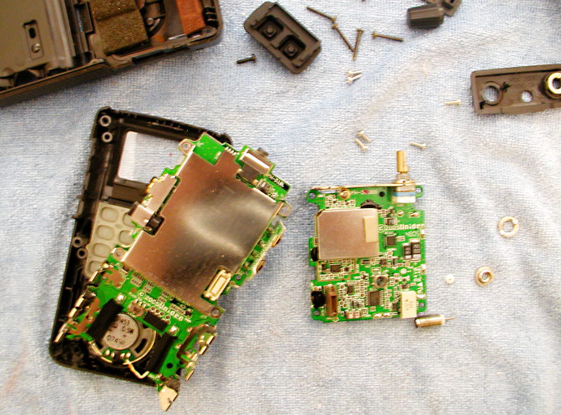
A trip to the Sprint Shack and I have a new connector in there and can use it as a radio again. But the jack I purchased is too short so I'm leaving most of the screws off until I can get the right part from Digikey. Might replace the speaker, too -- it has been sounding weak.
Also picked up some fabric and leather, Ritt dye and a couple pieces of poster board to use as seamless backdrops for model photography. Which is overkill for the size of most of my props these days:

That's my very first 3d print, BTW. Found the file on Thingiverse, printed it off in my new roll of pink SLA, then sanded the heck out of it. Tried three or four times to get a nice color on it. What seemed to sort of work was a primer coat of (bright yellow!) Rustoleum Super-Coat, followed by Tamiya Olive Drab2, then wet-sponging with a mixture of mostly pthalo green and burnt umber, with a couple of coats of gloss to cover.
The artists were inconsistent -- not only do promo pics not resemble the in-game prop, not only do neither resemble the official collectable shipped with the pre-order game, but it is rendered several different ways in game! That said, this is a pretty poor approximation of any of the versions, but it was fun to make.
And after all of that seamless-backdrop stuff, I still find I prefer taking prop pics with all sorts of random garbage in the image:

(That's a nautical clock, actually. And real charts, although I think they are Chesapeake Bay. And a far too modern and clean-looking reproduction firearm as well. I used to throw handfuls of NATO 5.56 crimps into the background, but I gave those away...)
Friday, July 10, 2015
Oops
Logged on to the Tormach CNC mill today.
On the plus side, I figured out how to use the software "wizards" to face a piece of stock on the Tormach itself (these are tiny sub-programs made available in many CNC tool drivers that allow semi-automated, semi-manual operations to be performed).
On the minus, my G-Code was bad. The code I'd sent from Fusion 360 wasn't useable. And the code from Cut3D -- well, despite being within the recommended tolerances, the moment I made my first machine pass it ramped down steeply and snapped my good end mill clean off.
Oh, yes. And the setscrew was completely stripped on the quick-collet when I got the machine (fortunately -- maybe fortunately -- I knew how to install a regular collet), and someone had left a stop secured to the vice...and it took fifteen minutes of searching the shop to find the right allen key to remove it.
This is the problem with a rental tool facility. The Tormach has the problems above. One of the two lathes is still out. Three of the 3d printers are dead. And the reservation calendar is starting to stretch for two weeks in advance.
I'm getting a real case of buyer's remorse here. I chose to pick up a year's membership at once because it was much cheaper. But that was a lump sum I really can't afford this month. I'm down to too little to pay bills. And nothing lined up to cover next month's rent.
Which is another reason to seriously rethink the Raygun prop. I think I need to turn to projects I know will earn money (I'm basically doing the Raygun at a loss) and come up with the cash to have the body printed at Shapeways instead of trying to machine it out.
(And, yes -- I could print it at TechShop, but it would take a week's worth of reservations and the tolerances wouldn't be as good. I've rather rethought the usefulness of being able to print there, as well. Printing is just too time consuming, and the lack of available machines and the short reservation period makes that a big problem.)
On the plus side, I figured out how to use the software "wizards" to face a piece of stock on the Tormach itself (these are tiny sub-programs made available in many CNC tool drivers that allow semi-automated, semi-manual operations to be performed).
On the minus, my G-Code was bad. The code I'd sent from Fusion 360 wasn't useable. And the code from Cut3D -- well, despite being within the recommended tolerances, the moment I made my first machine pass it ramped down steeply and snapped my good end mill clean off.
Oh, yes. And the setscrew was completely stripped on the quick-collet when I got the machine (fortunately -- maybe fortunately -- I knew how to install a regular collet), and someone had left a stop secured to the vice...and it took fifteen minutes of searching the shop to find the right allen key to remove it.
This is the problem with a rental tool facility. The Tormach has the problems above. One of the two lathes is still out. Three of the 3d printers are dead. And the reservation calendar is starting to stretch for two weeks in advance.
I'm getting a real case of buyer's remorse here. I chose to pick up a year's membership at once because it was much cheaper. But that was a lump sum I really can't afford this month. I'm down to too little to pay bills. And nothing lined up to cover next month's rent.
Which is another reason to seriously rethink the Raygun prop. I think I need to turn to projects I know will earn money (I'm basically doing the Raygun at a loss) and come up with the cash to have the body printed at Shapeways instead of trying to machine it out.
(And, yes -- I could print it at TechShop, but it would take a week's worth of reservations and the tolerances wouldn't be as good. I've rather rethought the usefulness of being able to print there, as well. Printing is just too time consuming, and the lack of available machines and the short reservation period makes that a big problem.)
Thursday, July 9, 2015
Keeping Tabs
The CAD file is complete and I have the CNC mill reserved for tomorrow. And I've run into two critical problems while setting up the actual tool paths.
The first is the growing realization that I won't be able to achieve the shapes that are on the CAD. Not, at least, without significant hand-work. There are too many curves and angles to make traditional milling possible, and the contour milling leaves too many fillets behind. So there is going to be time-consuming clean-up.
The critical one, at this moment, is a seemingly tiny problem. I can't set up support tabs in Fusion 360. Within, say, Cut3D the available tabs are primitive but they do the job:

Fusion 360 doesn't have that easy option. There are tabs in some of the milling operations, but they aren't global. And there are also some operations that can be instructed to stay clear of objects that could be part of a support structure. It may even be possible to define a set of tabs as a "fixture" -- I'm looking into that now.
But basically, I'm at a point of crawling through forums and watching endlessly slow, fatuously self-pleased instructional videos hoping that one of them may happen to mention this essential work-holding issue, and that it will be appropriate to the version of the software that I'm running (a perennial issue with Fusion 360, as they are re-writing it faster than anyone can document it).
Fortunately my fall-back is looking more plausible.
Cura (which is a freeware multi-platform "slicer" for 3d printing) estimates 1:58 to print the largest of my pieces. Which based on experience is about 1/2 the time the printer will actually take, but that still makes it just possible within a single machine reservation.
Even better, they all fall into the "within the density where calculations are performed on the bounding box" at Shapeways, to the point where all the major parts can be printed for under a hundred bucks total! If I had any spare cash at the moment, I'd probably put an order out right now just to be on the safe side...
I'm also depressed because I'm working sixteen hours a day trying to complete this commission and I'm flat broke. Can't even go look for work because, well, sixteen hour days trying to complete an existing commission. And the thing is really scaring me now. I don't know if I will be able to complete it (and it is already well behind on the delivery date I wanted.)
Well, maybe. If this thing gets done, I'll move on to the Jubal Early (which will be a lot easier based on what I've learned now). Heck..from what I've learned already, a PPG would be straight-forward. Perhaps even more straight-forward! If I can just survive a few more months, I just might be able to move on to some of the machined props people have been asking for. And one or two of those would pay my way for a considerable period...
The first is the growing realization that I won't be able to achieve the shapes that are on the CAD. Not, at least, without significant hand-work. There are too many curves and angles to make traditional milling possible, and the contour milling leaves too many fillets behind. So there is going to be time-consuming clean-up.
The critical one, at this moment, is a seemingly tiny problem. I can't set up support tabs in Fusion 360. Within, say, Cut3D the available tabs are primitive but they do the job:

Fusion 360 doesn't have that easy option. There are tabs in some of the milling operations, but they aren't global. And there are also some operations that can be instructed to stay clear of objects that could be part of a support structure. It may even be possible to define a set of tabs as a "fixture" -- I'm looking into that now.
But basically, I'm at a point of crawling through forums and watching endlessly slow, fatuously self-pleased instructional videos hoping that one of them may happen to mention this essential work-holding issue, and that it will be appropriate to the version of the software that I'm running (a perennial issue with Fusion 360, as they are re-writing it faster than anyone can document it).
Fortunately my fall-back is looking more plausible.
Cura (which is a freeware multi-platform "slicer" for 3d printing) estimates 1:58 to print the largest of my pieces. Which based on experience is about 1/2 the time the printer will actually take, but that still makes it just possible within a single machine reservation.
Even better, they all fall into the "within the density where calculations are performed on the bounding box" at Shapeways, to the point where all the major parts can be printed for under a hundred bucks total! If I had any spare cash at the moment, I'd probably put an order out right now just to be on the safe side...
I'm also depressed because I'm working sixteen hours a day trying to complete this commission and I'm flat broke. Can't even go look for work because, well, sixteen hour days trying to complete an existing commission. And the thing is really scaring me now. I don't know if I will be able to complete it (and it is already well behind on the delivery date I wanted.)
Well, maybe. If this thing gets done, I'll move on to the Jubal Early (which will be a lot easier based on what I've learned now). Heck..from what I've learned already, a PPG would be straight-forward. Perhaps even more straight-forward! If I can just survive a few more months, I just might be able to move on to some of the machined props people have been asking for. And one or two of those would pay my way for a considerable period...
Monday, July 6, 2015
Raygun XIII.II
So still haven't started cutting metal.
Been working hard to get there...pretty much exhausted myself; ended up crashing early on the evening of the 5th and sleeping over ten hours.
Where I am now, is where design for function, design for assembly, and design for manufacturing all butt heads. The shape of the gun is fairly fixed now; it's been through too many stages of prototyping and approval for me to make significant changes in dimension or shape. So I have to design the actual milled parts to support that shape.
Which also, of course, have to fit together. And it has to be possible to assemble them (not the same thing; this takes into account assembly order, tool access, and so forth). And they have to be manufacturable. Which is to say; I need to be able to create those shapes on the mill.
So one of the things I've been pushed into over this past week is to generate all my GCode in Fusion 360. There's one obvious utility; this means I can tweak the GCode right on my laptop during the actual milling session.
The stronger necessity, however, is to have better selection over which operations are performed on which part using which tool.
The CAM software I learned (and cut with) previously looks like this:

It is a friendly-looking interface, with helpful pictures. Fairly powerful, and even more advantageous, it has already made a lot of the more complicated decisions for you, presenting a simplified pallet of choices that is easy to navigate.
The CAM interface for Fusion 360 (which apparently is based around a fairly mature existing CAM package they licensed) looks like this:

There are a lot more options.
The advantages here are several; first, you have more algorithms (such as the spiral finishing path above) that can optimize speed and final finish. Even more importantly, there is a lot more choice in what you cut. In the above, the finishing pass is restricted to just the object itself; it isn't attempting to make passes through the entire bounding box.
But beyond that -- for several of the parts I have, I need to make sharp corners in order for them to fit together. But these same parts also have compound curves that need to be gone over in contour passes with a tiny ball-end end mill. Fusion gives me the opportunity to create specific operations that will place the flat end mill right into those right-angle corners, whilst leaving clearance for the finishing passes on the rounded bits.
More or less. It takes even more work to set all this up in the files. In a number of places I am better off re-thinking the mating surfaces so I don't have to do these passes this way.
And the big downside is I don't know what a lot of the options actually do. Which means I have a lot more work in setting up feeds and speed and clearances to make sure I'm not going to crash the head or do something else nasty and expensive.
Oh, yes. And I spent a while worrying about whether I could even get the end mill down into some of the deeper features (especially on the main body, which is over 1.5" wide). I looked up various end mills at Grainger and other companies, pulling down lots of numbers on available flute length (the real key to cut depth), as well as other numbers for stick-out and collet clearance.
And I'd forgotten that when I ran off my first test part, I'd already purchased my own starter set of mills. And the primary one has a nice generous flute length that is at least 1/8" larger than any of the ones I'd been looking at. Long enough, in fact, to have no trouble at all reaching down into the deepest pockets on my workpiece.
That still doesn't solve everything, though. There are still spots where the cut is going to end up rounded over, and I have to compensate for that in the mating surfaces. And there are still a few spots where I didn't think out the geometry properly and some of the cuts are actually impossible (as in, overhanging material). So I still have a few days of tinkering before the files are really ready.
And then when I hit the machines, I expect to find out a great deal more.
Been working hard to get there...pretty much exhausted myself; ended up crashing early on the evening of the 5th and sleeping over ten hours.
Where I am now, is where design for function, design for assembly, and design for manufacturing all butt heads. The shape of the gun is fairly fixed now; it's been through too many stages of prototyping and approval for me to make significant changes in dimension or shape. So I have to design the actual milled parts to support that shape.
Which also, of course, have to fit together. And it has to be possible to assemble them (not the same thing; this takes into account assembly order, tool access, and so forth). And they have to be manufacturable. Which is to say; I need to be able to create those shapes on the mill.
So one of the things I've been pushed into over this past week is to generate all my GCode in Fusion 360. There's one obvious utility; this means I can tweak the GCode right on my laptop during the actual milling session.
The stronger necessity, however, is to have better selection over which operations are performed on which part using which tool.
The CAM software I learned (and cut with) previously looks like this:

It is a friendly-looking interface, with helpful pictures. Fairly powerful, and even more advantageous, it has already made a lot of the more complicated decisions for you, presenting a simplified pallet of choices that is easy to navigate.
The CAM interface for Fusion 360 (which apparently is based around a fairly mature existing CAM package they licensed) looks like this:

There are a lot more options.
The advantages here are several; first, you have more algorithms (such as the spiral finishing path above) that can optimize speed and final finish. Even more importantly, there is a lot more choice in what you cut. In the above, the finishing pass is restricted to just the object itself; it isn't attempting to make passes through the entire bounding box.
But beyond that -- for several of the parts I have, I need to make sharp corners in order for them to fit together. But these same parts also have compound curves that need to be gone over in contour passes with a tiny ball-end end mill. Fusion gives me the opportunity to create specific operations that will place the flat end mill right into those right-angle corners, whilst leaving clearance for the finishing passes on the rounded bits.
More or less. It takes even more work to set all this up in the files. In a number of places I am better off re-thinking the mating surfaces so I don't have to do these passes this way.
And the big downside is I don't know what a lot of the options actually do. Which means I have a lot more work in setting up feeds and speed and clearances to make sure I'm not going to crash the head or do something else nasty and expensive.
Oh, yes. And I spent a while worrying about whether I could even get the end mill down into some of the deeper features (especially on the main body, which is over 1.5" wide). I looked up various end mills at Grainger and other companies, pulling down lots of numbers on available flute length (the real key to cut depth), as well as other numbers for stick-out and collet clearance.
And I'd forgotten that when I ran off my first test part, I'd already purchased my own starter set of mills. And the primary one has a nice generous flute length that is at least 1/8" larger than any of the ones I'd been looking at. Long enough, in fact, to have no trouble at all reaching down into the deepest pockets on my workpiece.
That still doesn't solve everything, though. There are still spots where the cut is going to end up rounded over, and I have to compensate for that in the mating surfaces. And there are still a few spots where I didn't think out the geometry properly and some of the cuts are actually impossible (as in, overhanging material). So I still have a few days of tinkering before the files are really ready.
And then when I hit the machines, I expect to find out a great deal more.
Thursday, July 2, 2015
Raygun XIII.I
The worst of the CAD is done:

That's the right side of the main body. About all I have left is putting the screw holes in the mating piece, finishing the "energy cell" release on the bottom of the grip, and doing a last pass to add slop and tolerance where possible. Pity many of the cuts are not at right angles; makes it hard to do clean-up with traditional machining.
And I may still add an overlap for visual effect.
I'm liking Fusion 360 more and more. Once you get used to the program flow, it moves very quickly. Shapes -- primitives or what they call "sketch" shapes -- snap to existing edges and faces making it really simple to line up near-seamless additions or cuts. Faces are intelligent; you can drag them around and they remember what they were trying to do based on the geometry they were originally a part of. For instance, if I were to select one face of the sounding board and drag it, it would re-fit itself to the inner curve of the body shell as I dragged it. Within reason, of course!
And the CAM section is very complete, with lots of choices in path and work setup. I may actually CAM from Fusion, instead of from Cut3d. And just in case that wasn't enough, they also throw in a pretty decent ray-trace render!
So why is the piece above so complicated?

Because almost all of the components fit into it. This is the keel of the gun; all the parts screw down to it so I can finish and test the electronics before closing the other half of the body over it all. And, yes, there's rather a lot of compromise here. The surface transducer, especially, is facing a 1/16" aluminium panel that is split in two pieces to allow the gun to come apart. I have no idea how it is going to sound.
The Cree also lacks the heat sink I wanted to add; it is nested on the face side (meaning I'll have to protect the wires) instead of making contact with bare metal. And as I said there's barely room for even the wiring between the parts.
And there's way too many screws that need tapping (not in the model; the screws holding the switch down, pegging the spring, and as part of the pivot for the trigger.)
Since the CAM software will attempt to cut everything that is presented in the file, I'm leaving the screw holes out (except for the large holes the heads sink into). So if I go with 3d printing I'll need to fork the file or duplicate the parts that need screw holes printed into them. And I might make another pass for holes, with a bit change or two, but I'm going to be pushing just to get a full piece run off on the Tormach before each day's reservation runs out.


That's the right side of the main body. About all I have left is putting the screw holes in the mating piece, finishing the "energy cell" release on the bottom of the grip, and doing a last pass to add slop and tolerance where possible. Pity many of the cuts are not at right angles; makes it hard to do clean-up with traditional machining.
And I may still add an overlap for visual effect.
I'm liking Fusion 360 more and more. Once you get used to the program flow, it moves very quickly. Shapes -- primitives or what they call "sketch" shapes -- snap to existing edges and faces making it really simple to line up near-seamless additions or cuts. Faces are intelligent; you can drag them around and they remember what they were trying to do based on the geometry they were originally a part of. For instance, if I were to select one face of the sounding board and drag it, it would re-fit itself to the inner curve of the body shell as I dragged it. Within reason, of course!
And the CAM section is very complete, with lots of choices in path and work setup. I may actually CAM from Fusion, instead of from Cut3d. And just in case that wasn't enough, they also throw in a pretty decent ray-trace render!
So why is the piece above so complicated?

Because almost all of the components fit into it. This is the keel of the gun; all the parts screw down to it so I can finish and test the electronics before closing the other half of the body over it all. And, yes, there's rather a lot of compromise here. The surface transducer, especially, is facing a 1/16" aluminium panel that is split in two pieces to allow the gun to come apart. I have no idea how it is going to sound.
The Cree also lacks the heat sink I wanted to add; it is nested on the face side (meaning I'll have to protect the wires) instead of making contact with bare metal. And as I said there's barely room for even the wiring between the parts.
And there's way too many screws that need tapping (not in the model; the screws holding the switch down, pegging the spring, and as part of the pivot for the trigger.)
Since the CAM software will attempt to cut everything that is presented in the file, I'm leaving the screw holes out (except for the large holes the heads sink into). So if I go with 3d printing I'll need to fork the file or duplicate the parts that need screw holes printed into them. And I might make another pass for holes, with a bit change or two, but I'm going to be pushing just to get a full piece run off on the Tormach before each day's reservation runs out.

Wednesday, July 1, 2015
Raygun XIII
I've finally hit the part of the CAD I thought might take a little time. Just as I'd reached the point in project scheduling where I was hoping to blow through and not take a lot of time, of course.
To wit; not just getting all the parts connected, but fitting all the internal mechanisms in there:


To wit; not just getting all the parts connected, but fitting all the internal mechanisms in there:

There is surprisingly little space. I thought, since I was creating the shell from scratch instead of depending on the vagaries of slush-casting, I'd have a lot more wiggle room. But there's not even room for the battery capacity I want.
At least I'd foreseen having issues with the trigger. I was smart enough to make a scaled mock-up, complete with spring and stop pins:

If I'd been at the shop I would have laser-cut these pieces from the actual file. As it is, they were achieved through the high-tech method of tracing directly off the computer screen. And then I wasted more time figuring out how joints work in Fusion 360 so I could test the completed action in software.
Notice how many iterations I had to go through before I found a working compromise between room for the finger, a decent take-up, and a comfortable action.
Of course getting all the other parts into CAD took a little time with calipers (I actually ran down to the hardware store to make sure I was measuring the exact hardware that would be available at assembly time):

The electronics are from both Adafruit and DigiKey, with a last-minute replacement of the limit switch with one with a stiffer action from, of all places, "Sprint-Shack." Oh, and yes; that's a quick CAD mock-up of my own DuckNode LED controller. Which only barely fits -- this thing really is tight inside.
Of course all these complicated shapes do no-one any good if they can't be manufactured. So as another sanity check, I set up several simulated CNC runs in Fusion itself (I'll probably be working up the actual G-code in the simpler Cut3d). There were various issues with fouling the tools, but with end mills at the longer end of the range I was able to get all the cuts completed -- and get a sense of how much the final aluminium is going to vary from the CAD version (and important question when there are so many pieces fitting so tightly together!)

And maybe CNC isn't the answer. Besides the way that all the corners will be rounded over (unless I spend even more effort with pencil mills and hand files and so forth), there's the matter of time and the cost of tooling. So...will Fusion 360 export in a file format Shapeways will accept, and what is the cost of printing these parts there?

It will, and, oddly affordable. Using the aluminium-powder infused SLA as rendered by Shapeways, above, that piece alone is $40, meaning the entire gun could probably be run off for around $160. And the only real change to the files is to put the bolt holes in, but set them for the self-tapping qualities of sheet metal screws.
So it will work. If I can't CNC it, I can print it. And although it is a tight fit, there's nothing critical about the electronics. Well, except maybe for the speaker. I'm also having a lot of questions about whether that surface transducer is actually going to work. I flirted for a number of hours today (I guess this was a long day!) with having a separate "sounding board" that was fit into the gun and secured with JB Weld, but the theory is really that the whole gun becomes a vibrating surface, and there really wasn't room anyhow.
Lastly -- this has been a rather busy week, really -- I made it out to TechShop for a class on the ShopBot. So now I'm checked out on a machine that can rough a 3d shape out of MDF very quickly, working off a good 3d model. Which was all along a possible approach for this thing; do an MDF master, then use it as a buck to pull ABS on the vacuum-former, or mold it up and slush-cast in plastic.
Monday, June 29, 2015
Fusing
I'm really starting to like Fusion360. At least, for parametric models. I have no idea what it looks like in mesh and whether the output would be useable in the Poserverse. One big one; unlike my usual mesh modeler (Carrara), booleans work great in Fusion. In fact, booleans are emphasized by the software.
So I'm making pretty good progress figuring out all the internal bits and pieces that hold the raygun together and put the electronic parts where they need to be:


After that the project moved into CAD. More problems had to be solved within CAD, and I made several changes -- some of them accidental, such as the new direction of the grip texture. More emails back and forth. I also went to Urban Ore to look at old drills and similar tools to brush up on appropriate assembly details. But at last, the outer shape was set. This is a quick render from inside Fusion360:

And now the internals are getting finished up in the CAD -- this week I'll finally be able to start cutting metal:
And since the mock-up had been useful getting to this point, I spent a little time modifying it to reflect the new shape:

Don't mourn -- it will get all smoothed out again. (And next time I do something like this, it will be done with MDF and Bondo so it can take details properly and hold up to the rigors of casting or forming). The mock-up is better already; it is pink now:

Oh, yes. And I shipped the latest grenade order, bringing the total number of Aliens M40's I've made and sold to....44. Which would look something like this, if I still had any of them here:

So I'm making pretty good progress figuring out all the internal bits and pieces that hold the raygun together and put the electronic parts where they need to be:

As a little recap; this is a commission prop, with a firm due-date (now less than seven weeks away). The spec was a retro-looking raygun; "Jetsons, but as if it were real." Thus metal-body construction and exposed hardware.
After several weeks of sketches we hit on the right look:
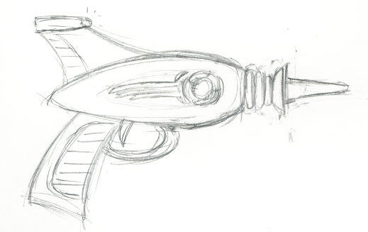
The first thing I made was a paper mock-up, extrapolating from various gun-like objects I had around the house to scale the grip and body. That mock-up showed the dimensions needed a little more tweaking:

Next, to help visualize the thing, I made a second scale drawing, cut that drawing out of foam-core, and when the dimensions seemed decent, padded up the foam-core with expanded polystyrene:

Sanded down, smoothed out, painted silver, it gave me a good sanity check on the shape and I could let the client hold it and see how it looked on her. I made a few notations at this point for adjustment to some of the dimensions:


And now the internals are getting finished up in the CAD -- this week I'll finally be able to start cutting metal:

Don't mourn -- it will get all smoothed out again. (And next time I do something like this, it will be done with MDF and Bondo so it can take details properly and hold up to the rigors of casting or forming). The mock-up is better already; it is pink now:

Oh, yes. And I shipped the latest grenade order, bringing the total number of Aliens M40's I've made and sold to....44. Which would look something like this, if I still had any of them here:

Thursday, June 25, 2015
RaygunXII.III
I forked the CAD file, tried out several variations, emailed the client...and I think I've boiled down a little to a tweaked version that maintains things I liked about the prototype while still walking that line between maintaining that recognizable "Jetsons" ancestry but looking solid and practical:

I just can't get the insulator "donuts" any bigger without it feeling unbalanced. But the less busy fin and the longer "swoosh" and smaller dish are helping a lot, I think. I'm trying to keep some hints of 1950's propmaster here, but the "jewels" (marking intensity settings) were just a little too much in that direction. Besides...the unmarked dial means I can put any arbitrary number of behaviors into the software.
I keep wandering off into elaborate sidetracks, like the idea of a remove-able energy cell. As of the moment, I'm reserving the option but the access plate in the pistol butt is just going to be there to get at the USB charge cable. I'm also having a lot of trouble thinking in 2.5d.
Here's the thing; the majority of this is going to be run off on a CNC mill. I'm flipping parts once to do the back sides, but that means every cut I make has to be possible to reach from one side or the other. Took me forever to wrap my mind around how the catch for the butt plate works, until I finally saw that from the viewpoint of the mill, where the catch needs to go looks like a slot.
I have forty pages of sketches brainstorming the various mechanical details. But of course how they actually work out gets revealed in the CAD. The assembly details of the front don't look right in the CAD, for instance; the sketches had a more generous space for tapped holes. So I'm wobbling right now on a range all the way from woodruff keys to threading down to just throwing JB Weld in there and doing a friction fit.
The electromechanical components are all here now; medium surface transducer, lever (limit) switch, potentiometer with integral twist switch, 3W pink Cree. The metal (and acrylic) is here as well. Sigh. Always something -- a 3/8" acrylic rod would fit right in with minimal lathing necessary. But the acrylic I want isn't available in that diameter. So I need to lathe the length of the rod, which is again unexplored territory.
Doesn't help that I had a grenade order that got delayed by the unexpected dance show. I finally finished lathing them today. I'm ambivalent there as well. I have learned so much since the first orders, and on average the quality of the work continued to improve. But at the same time my patience for achieving that possible quality is slipping. I'm skipping more steps and going "good enough" more often than I should. Doesn't help that it took 10 hours over three different trips to the shop to make just four grenades -- for merely $160, as I was doing a bulk savings offer as long as the leftover metal from the last big order lasted.
Which is why I'm seriously considering another lighting hang in Mountain View, despite it being a three hour commute each way. I'm saving a big chunk now on my TechShop membership -- got a year membership at one go. But that means my cash is dropping down towards critical again.
But with seven weeks to go until drop-dead delivery date, I simply have to push aside my financial woes and move the raygun forward. At least the CAD is finally moving properly. With luck I'll be ready to start cutting metal by this weekend.

I just can't get the insulator "donuts" any bigger without it feeling unbalanced. But the less busy fin and the longer "swoosh" and smaller dish are helping a lot, I think. I'm trying to keep some hints of 1950's propmaster here, but the "jewels" (marking intensity settings) were just a little too much in that direction. Besides...the unmarked dial means I can put any arbitrary number of behaviors into the software.
I keep wandering off into elaborate sidetracks, like the idea of a remove-able energy cell. As of the moment, I'm reserving the option but the access plate in the pistol butt is just going to be there to get at the USB charge cable. I'm also having a lot of trouble thinking in 2.5d.
Here's the thing; the majority of this is going to be run off on a CNC mill. I'm flipping parts once to do the back sides, but that means every cut I make has to be possible to reach from one side or the other. Took me forever to wrap my mind around how the catch for the butt plate works, until I finally saw that from the viewpoint of the mill, where the catch needs to go looks like a slot.
I have forty pages of sketches brainstorming the various mechanical details. But of course how they actually work out gets revealed in the CAD. The assembly details of the front don't look right in the CAD, for instance; the sketches had a more generous space for tapped holes. So I'm wobbling right now on a range all the way from woodruff keys to threading down to just throwing JB Weld in there and doing a friction fit.
The electromechanical components are all here now; medium surface transducer, lever (limit) switch, potentiometer with integral twist switch, 3W pink Cree. The metal (and acrylic) is here as well. Sigh. Always something -- a 3/8" acrylic rod would fit right in with minimal lathing necessary. But the acrylic I want isn't available in that diameter. So I need to lathe the length of the rod, which is again unexplored territory.
Doesn't help that I had a grenade order that got delayed by the unexpected dance show. I finally finished lathing them today. I'm ambivalent there as well. I have learned so much since the first orders, and on average the quality of the work continued to improve. But at the same time my patience for achieving that possible quality is slipping. I'm skipping more steps and going "good enough" more often than I should. Doesn't help that it took 10 hours over three different trips to the shop to make just four grenades -- for merely $160, as I was doing a bulk savings offer as long as the leftover metal from the last big order lasted.
Which is why I'm seriously considering another lighting hang in Mountain View, despite it being a three hour commute each way. I'm saving a big chunk now on my TechShop membership -- got a year membership at one go. But that means my cash is dropping down towards critical again.
But with seven weeks to go until drop-dead delivery date, I simply have to push aside my financial woes and move the raygun forward. At least the CAD is finally moving properly. With luck I'll be ready to start cutting metal by this weekend.
Wednesday, June 24, 2015
Raygun VII.II
The CAD has been fighting me. I always love tutorials from the people bankrolling the software; it is extremely rare when they openly admit they are only doing the kinds of shapes the software wants, and letting it make their design choices for them. A luxury I mostly do not have, as this project has proceeded through a careful series of pre-production sketches, concept models, and so on -- with client approval at each step.

In any case, the surface detailing is basically done. I've also been struggling -- pretty much, throughout the design process -- with balancing the sleek menace of a "real" looking weapon, with the kind of playful, puffed-up cartoony look we are after. I may have been looking at this model too long, but right now frankly I prefer the mock-up:
It has a sleeker feel to it. Some appears unavoidable consequences of the tooling up; the client requested the "donuts" be larger and more prominent, for instance (which felt like it required a larger dish as well). The setting knob has to be bigger in order to get fingers inside it (although I suppose I could use a knob with a knurled outer edge instead -- or even go with a chicken-head instead of the 1970's television dial style recessed disk). And the new direction of the cuts in the grip was an accident, but I think it looks better. It does, however, pull away from the strong horizontal flow of the prop.
Even the fin almost looks better as a flat slab, instead of the sculpted airplane tailfin I had originally envisioned.
But there's only seven weeks until delivery. That's already far short of my original target of having a month for the client to show it off and maybe inspire some friends to purchase their own. So I can no longer afford to do a lot of second-guessing. Including with the software; I have to accept the ways it is forcing the shapes to go and live with that.

In any case, the surface detailing is basically done. I've also been struggling -- pretty much, throughout the design process -- with balancing the sleek menace of a "real" looking weapon, with the kind of playful, puffed-up cartoony look we are after. I may have been looking at this model too long, but right now frankly I prefer the mock-up:
It has a sleeker feel to it. Some appears unavoidable consequences of the tooling up; the client requested the "donuts" be larger and more prominent, for instance (which felt like it required a larger dish as well). The setting knob has to be bigger in order to get fingers inside it (although I suppose I could use a knob with a knurled outer edge instead -- or even go with a chicken-head instead of the 1970's television dial style recessed disk). And the new direction of the cuts in the grip was an accident, but I think it looks better. It does, however, pull away from the strong horizontal flow of the prop.
Even the fin almost looks better as a flat slab, instead of the sculpted airplane tailfin I had originally envisioned.
But there's only seven weeks until delivery. That's already far short of my original target of having a month for the client to show it off and maybe inspire some friends to purchase their own. So I can no longer afford to do a lot of second-guessing. Including with the software; I have to accept the ways it is forcing the shapes to go and live with that.
Monday, June 22, 2015
Raygun VII.I
This project is scaring me. I'm tempted to bail on the all-metal version and switch to making a nice sculpt. CAD is going depressingly slow, and I am filled with concern about the extent of the unknowns in the process.
Plus even though the CNC step is the big one, there is a good week of work in electronics and in the plastic parts, each.
So finally got the details cut into the pistol grip. On the surface, simple enough; create a spline, turn it into a pipe and use that as a tool to make a boolean cut. Except not, of course. I haven't found any shrink-wrap or surface following in Fusion3D yet -- only the ability to snap a point to an existing point or plane (which half the time ends up adding the point to the previous sketch or body or whatever.)
And the way that operations are supposed to stack in history...meaning you could edit the spline curve to correct the look of the cut...well, that didn't work. So I had to do the cuts by trial and error. And that was after sort of figuring out how the spline tools work (apparently there are at least two different edit modes. In one, constraints show up as icons that can be deleted. In the other, constraints do not display and the only way you can figure out if they are there is by toggling them on then toggling them off again. For every single selectable point.
The other mild success is I hooked up the 2.5 watt mono amp to the surface transducer, and taped it down to a nice solid chunk of machinery (a nautical clock I happen to own). And it was pleasingly loud, especially when I hit some natural resonances. Probably not loud enough to be impressive at a convention, but with luck this will work for the prop. I'm starting to get concerned about interior space, though. The transducer takes up a big chunk of space and there's not a large hole between where the trigger mechanism has to go and where the potentiometer is mounted for the knob.
Oh, yes. I also ordered pot, trigger switch, a rotary switch in case I change my mind...and the metal. Hopefully the CAD won't suddenly call for stock dimensions larger than I estimated.
Thursday, June 11, 2015
Fusion Cooking
So I'm officially behind on the Raygun. My target was to start cutting metal this week. Work showed up instead, good work -- did one morning gig hanging lights (actually, spent most of the time driving the scissor lift around) for a clean $100 in cash.
From the money from the most recent grenade order I dropped fifty on a new tool holder from Grizzly. It looks good, all solid (and very oily!) metal, but I've experienced some unusually soft steel before. Such as the bench vise I got from OSH that has disabused me from ever buying a vise from that store again.
But even taking all this into account the CAD is going terribly slow. Part of that is learning the software. The greater part is having to solve so many design issues. Metal is a bit unforgiving. I can make a few adjustments for poor fit-up or other errors, but it is slow work correcting mistakes made in metal. Metal is hard, slow to shape and requiring power tools to do so. And expensive. I really need to anticipate as many issues as possible and solve them before I start cutting metal.
It is engineering. It is a balancing act. Trying to balance aesthetics, strength, and manufacturability. Out of the many things you have to do to engineer something properly is to compensate for various sources of error. You design in steps that will catch and correct (such as my current M40 lathing scheme, which holds 4/1000 in reserve for a finishing pass; this picks up and corrects various places where tools like the knurl or the parting tool deform the grenade, throwing up ridges of excess metal behind them).
A subtler one is how I run a de-burr tool around the edge of the hole before inserting the button; this produces an expansion space for the metal to flow into when I crush the plug in with the press. In previous grenades, this edge was forced into the button pin, pinching it.
The other major tool in dealing with the inevitable errors in measurement, tool wobble, manufacturing variance, etc., is to not design around perfection in the first place. I really had this demonstrated for me during discussions of the Apollo Program and the absurd suggestion that "the landings" were faked in a film studio. One of the claims the believers in a hoax make is that the necessary positional accuracy of the original launch is impossible to achieve. The slightest fraction of a degree off at launch, they argue, and the spacecraft would be multiple kilometers off target by the time it reaches the Moon.
Which is why the NASA engineers -- like any engineers -- did no such thing. They simply pointed the spacecraft "good enough" to get within the circle of error of the next designed-in correction stage. One equivalent in design for assembly is you use a slot or an over-sized hole on the upper piece, so the bolt will still go in and hold everything properly even if there is some slop in machining or alignment. You don't design so the holes must be perfectly aligned...unless there are other design goals requiring it.
But this has to be of course designed in. Even at the simplest level, design for manufacture means you have to solve endless "duck, wolf, bag of grain" problems, where part C is bolted over the bolt holding part A to part B -- fixing the assembly order and making it impossible to place bolt holes for C on the inside of A.
My raygun nozzle is currently there. The reflector dish is CNC'd out of plate stock, top and bottom pass (which themselves brings up the question of how good my alignment will be). On the final pass I'll machine a hole all the way through, and push a lathed spindle through that. The acrylic nozzle goes inside that spindle and all the way into the gun to reach the Cree that illuminates it, and ends up supporting the front assembly.
After working on it off and on for over a week, and covering several pages of graph paper with mechanical sketches, I've figured out the connections and assembly order. The spindle is one-way (it has a lip) and will have a tapped hole in the side behind the dish which holds a screw pressing into the acrylic. The dish is pushed against the spindle from the other side by the pressure of the 3d-printed insulator rings -- which also are floating freely on the rod -- and the whole Dagwood Sandwich is pinned together by a second screw at the gun end. Which, since the front end of the gun tapers, is on the outside of the shell, and since the insulator rings are there, is accessed for tightening by a hole in the insulator rings that you can fit an allen key through.
There are a lot of alternatives I had to reject, and a lot of secondary considerations. Could machine the spindle as part of the dish but it would look better lathed. And take a lot more metal to machine from a single block of material. The dish can't be lathed (wrong kind of curves) but it can be lathe-polished. Which means the assembly is designed so I can put both parts together and chuck that in the lathe before removing a metal central rod and putting the acrylic in. In addition, any error in the length of any of these parts is adjusted for at the gun end, where the final retainer is.
And, yes, the acrylic is a failure point. But if I added metal -- well, extending the spindle to the gun is possible but the thickness is determined by the aesthetics at the nozzle end, and still creates a potential weak point. Inserting a stainless steel tube strengthens it, but requires the acrylic nozzle have a step to cover the diameter change, and that becomes the point of failure. This way, replacing the nozzle in case of breakage is less onerous, and I'll simply have to put up with the fact that the reflector dish provides a good lever to put stress on it.
(And, yes, I could switch to polycarb, but it is tougher to machine and although stronger, more likely to leave dangerous edges when it fails under stress.)
I've more-or-less solved the front assembly, how the handle fits together, the fin assembly, the trigger guard. But I still have to finish designing the trigger assembly, the access plate/removeable power cell that will allow uncoiling the USB cable to recharge the internal LiPo, how to get the LED wired into the fin...and I haven't even touched the side panels with their switch, indicator lights, and swoosh.
And very few of these assembly details are reflected in the CAD as of yet -- which I fully expect is going to reveal other potential problems in fit-up and assembly, as well as mechanical weaknesses and structures which are un-machinable as they stand. (I'm not about to get into 4-axis CNC at this point, so I basically have to make shapes that can be attacked from two sides at a maximum, plus traditional machining -- milling and drilling -- at off-axis to these. And, yes; every threaded hole I add is a manual operation; hand-tapping.)
Oh and yeah. My cheap eats these days is a three-day curry; 1 "can" Coconut Milk (I like the "school-lunch milk" boxes from Kara; very rich and fatty), red curry paste (May Ploy brand; comes in a tub like miso paste), tofu and veggies to suit (I get locally-made extra-firm tofu sold bulk-style at Berkeley Bowl). Often Dynasty sliced water chestnuts, cut baby corn -- but I've also used carrots, broccoli florets, canned bamboo shoots, and fresh snow peas. Plus a can of Albacore tuna if I can afford it. Makes three servings...I brew up 1-2 cups of jasmine rice in the rice cooker and re-heat the curry for a meal. Goes nice with a rooibos chai (also bought in the bulk produce section).
From the money from the most recent grenade order I dropped fifty on a new tool holder from Grizzly. It looks good, all solid (and very oily!) metal, but I've experienced some unusually soft steel before. Such as the bench vise I got from OSH that has disabused me from ever buying a vise from that store again.
But even taking all this into account the CAD is going terribly slow. Part of that is learning the software. The greater part is having to solve so many design issues. Metal is a bit unforgiving. I can make a few adjustments for poor fit-up or other errors, but it is slow work correcting mistakes made in metal. Metal is hard, slow to shape and requiring power tools to do so. And expensive. I really need to anticipate as many issues as possible and solve them before I start cutting metal.
It is engineering. It is a balancing act. Trying to balance aesthetics, strength, and manufacturability. Out of the many things you have to do to engineer something properly is to compensate for various sources of error. You design in steps that will catch and correct (such as my current M40 lathing scheme, which holds 4/1000 in reserve for a finishing pass; this picks up and corrects various places where tools like the knurl or the parting tool deform the grenade, throwing up ridges of excess metal behind them).
A subtler one is how I run a de-burr tool around the edge of the hole before inserting the button; this produces an expansion space for the metal to flow into when I crush the plug in with the press. In previous grenades, this edge was forced into the button pin, pinching it.
The other major tool in dealing with the inevitable errors in measurement, tool wobble, manufacturing variance, etc., is to not design around perfection in the first place. I really had this demonstrated for me during discussions of the Apollo Program and the absurd suggestion that "the landings" were faked in a film studio. One of the claims the believers in a hoax make is that the necessary positional accuracy of the original launch is impossible to achieve. The slightest fraction of a degree off at launch, they argue, and the spacecraft would be multiple kilometers off target by the time it reaches the Moon.
Which is why the NASA engineers -- like any engineers -- did no such thing. They simply pointed the spacecraft "good enough" to get within the circle of error of the next designed-in correction stage. One equivalent in design for assembly is you use a slot or an over-sized hole on the upper piece, so the bolt will still go in and hold everything properly even if there is some slop in machining or alignment. You don't design so the holes must be perfectly aligned...unless there are other design goals requiring it.
But this has to be of course designed in. Even at the simplest level, design for manufacture means you have to solve endless "duck, wolf, bag of grain" problems, where part C is bolted over the bolt holding part A to part B -- fixing the assembly order and making it impossible to place bolt holes for C on the inside of A.
My raygun nozzle is currently there. The reflector dish is CNC'd out of plate stock, top and bottom pass (which themselves brings up the question of how good my alignment will be). On the final pass I'll machine a hole all the way through, and push a lathed spindle through that. The acrylic nozzle goes inside that spindle and all the way into the gun to reach the Cree that illuminates it, and ends up supporting the front assembly.
After working on it off and on for over a week, and covering several pages of graph paper with mechanical sketches, I've figured out the connections and assembly order. The spindle is one-way (it has a lip) and will have a tapped hole in the side behind the dish which holds a screw pressing into the acrylic. The dish is pushed against the spindle from the other side by the pressure of the 3d-printed insulator rings -- which also are floating freely on the rod -- and the whole Dagwood Sandwich is pinned together by a second screw at the gun end. Which, since the front end of the gun tapers, is on the outside of the shell, and since the insulator rings are there, is accessed for tightening by a hole in the insulator rings that you can fit an allen key through.
There are a lot of alternatives I had to reject, and a lot of secondary considerations. Could machine the spindle as part of the dish but it would look better lathed. And take a lot more metal to machine from a single block of material. The dish can't be lathed (wrong kind of curves) but it can be lathe-polished. Which means the assembly is designed so I can put both parts together and chuck that in the lathe before removing a metal central rod and putting the acrylic in. In addition, any error in the length of any of these parts is adjusted for at the gun end, where the final retainer is.
And, yes, the acrylic is a failure point. But if I added metal -- well, extending the spindle to the gun is possible but the thickness is determined by the aesthetics at the nozzle end, and still creates a potential weak point. Inserting a stainless steel tube strengthens it, but requires the acrylic nozzle have a step to cover the diameter change, and that becomes the point of failure. This way, replacing the nozzle in case of breakage is less onerous, and I'll simply have to put up with the fact that the reflector dish provides a good lever to put stress on it.
(And, yes, I could switch to polycarb, but it is tougher to machine and although stronger, more likely to leave dangerous edges when it fails under stress.)
I've more-or-less solved the front assembly, how the handle fits together, the fin assembly, the trigger guard. But I still have to finish designing the trigger assembly, the access plate/removeable power cell that will allow uncoiling the USB cable to recharge the internal LiPo, how to get the LED wired into the fin...and I haven't even touched the side panels with their switch, indicator lights, and swoosh.
And very few of these assembly details are reflected in the CAD as of yet -- which I fully expect is going to reveal other potential problems in fit-up and assembly, as well as mechanical weaknesses and structures which are un-machinable as they stand. (I'm not about to get into 4-axis CNC at this point, so I basically have to make shapes that can be attacked from two sides at a maximum, plus traditional machining -- milling and drilling -- at off-axis to these. And, yes; every threaded hole I add is a manual operation; hand-tapping.)
Oh and yeah. My cheap eats these days is a three-day curry; 1 "can" Coconut Milk (I like the "school-lunch milk" boxes from Kara; very rich and fatty), red curry paste (May Ploy brand; comes in a tub like miso paste), tofu and veggies to suit (I get locally-made extra-firm tofu sold bulk-style at Berkeley Bowl). Often Dynasty sliced water chestnuts, cut baby corn -- but I've also used carrots, broccoli florets, canned bamboo shoots, and fresh snow peas. Plus a can of Albacore tuna if I can afford it. Makes three servings...I brew up 1-2 cups of jasmine rice in the rice cooker and re-heat the curry for a meal. Goes nice with a rooibos chai (also bought in the bulk produce section).
Saturday, May 9, 2015
Pictures soon...
Atrociously slow work on the Space Helmet. I'm worried -- the deadline on the Raygun is getting far too close for comfort, and I really want some Holocrons in the RPF sales section. I need the money!
Took a plaster cast off the fitted eye lenses. Something reacted to the clear acrylic, though. Might have been the mold release, or the cast itself. They came out yellowed and didn't cure properly. The mold, of course, did not survive demoulding, but the casts are good enough (after a test fit) to make another mold off them. Unfortunately the last of my Oomoo-30 set up in the jar, leaving me with nothing but a bit of Rebound-25 to try to take a new cast.
I did use a little of the excess casting resin to coat and reinforce the PETG pull of the mask, though, plus put some divots in a chunk of clay and cast some possible rivet heads. Once I get the side pieces cut out the rest should go fast. Sigh. Been hard enough getting laser time together, I'm tempted to grab a sheet of heavy styrene and hand-cut them from that.
On the Holocron side, Novus #2 appears to restore the clear acrylic panels after flaws (glue spots and melted overflow from the laser cutting) have been sanded down. It takes a lot of it and a fair amount of work, though. Power buffing did not work; even at low speed my Dremel melted right into the plastic and made nasty grooves. It is possible a large buffing wheel would do better, but I'd have to find a clean one that hadn't been used to buff freshly-welded metal (which seems to rule out using the one at TechShop!)
I'm still not entirely happy with the Temple design. Worse, I haven't been able to come up with a new design I really like. So I'm still pretty far away from having samples for any new Holocrons.
On the Raygun, the surface-mount driver I was waiting on showed up and I've experimented briefly with it. Still can't tell if it is going to work. The problem here is the body of the gun is way too large to permit iterative design. I need to figure out everything in the 3d model and cut exactly that, since the CNC machining step is going to take upwards of eight hours of solid machine time.
All I can say right now on the driver is, from experiments putting it inside pots, ukulele, unfinished holocrons, and the like, it will at least make a noise. It may turn out to be necessary to not just mill some speaker slots in the gun, but re-cut the speaker mounting after machining the gun.
I'm also procrastinating on the trigger design. I wish I had just picked a button I knew would be a common stock item, so I could pop that into the CAD. Well, Fusion 360 does allow importing of parts from various sources, but in this case I'd feel better if I could hold the part in my hands and feel how the trigger motion works. Maybe I need to add making a mock-up to my growing list of laser needs?
At least I think I've solved the repro issue. Assuming I am making a limited number of ray guns serially, I will 3d-print them myself over at TechShop. The lower quality of the prints there is fine because the outer surface is all smooth curves anyhow -- no real problem in just sanding the heck out of it.
Took a plaster cast off the fitted eye lenses. Something reacted to the clear acrylic, though. Might have been the mold release, or the cast itself. They came out yellowed and didn't cure properly. The mold, of course, did not survive demoulding, but the casts are good enough (after a test fit) to make another mold off them. Unfortunately the last of my Oomoo-30 set up in the jar, leaving me with nothing but a bit of Rebound-25 to try to take a new cast.
I did use a little of the excess casting resin to coat and reinforce the PETG pull of the mask, though, plus put some divots in a chunk of clay and cast some possible rivet heads. Once I get the side pieces cut out the rest should go fast. Sigh. Been hard enough getting laser time together, I'm tempted to grab a sheet of heavy styrene and hand-cut them from that.
On the Holocron side, Novus #2 appears to restore the clear acrylic panels after flaws (glue spots and melted overflow from the laser cutting) have been sanded down. It takes a lot of it and a fair amount of work, though. Power buffing did not work; even at low speed my Dremel melted right into the plastic and made nasty grooves. It is possible a large buffing wheel would do better, but I'd have to find a clean one that hadn't been used to buff freshly-welded metal (which seems to rule out using the one at TechShop!)
I'm still not entirely happy with the Temple design. Worse, I haven't been able to come up with a new design I really like. So I'm still pretty far away from having samples for any new Holocrons.
On the Raygun, the surface-mount driver I was waiting on showed up and I've experimented briefly with it. Still can't tell if it is going to work. The problem here is the body of the gun is way too large to permit iterative design. I need to figure out everything in the 3d model and cut exactly that, since the CNC machining step is going to take upwards of eight hours of solid machine time.
All I can say right now on the driver is, from experiments putting it inside pots, ukulele, unfinished holocrons, and the like, it will at least make a noise. It may turn out to be necessary to not just mill some speaker slots in the gun, but re-cut the speaker mounting after machining the gun.
I'm also procrastinating on the trigger design. I wish I had just picked a button I knew would be a common stock item, so I could pop that into the CAD. Well, Fusion 360 does allow importing of parts from various sources, but in this case I'd feel better if I could hold the part in my hands and feel how the trigger motion works. Maybe I need to add making a mock-up to my growing list of laser needs?
At least I think I've solved the repro issue. Assuming I am making a limited number of ray guns serially, I will 3d-print them myself over at TechShop. The lower quality of the prints there is fine because the outer surface is all smooth curves anyhow -- no real problem in just sanding the heck out of it.
Subscribe to:
Posts (Atom)