Show is open, and I'm running FOH for the duration. So I've got a bit over a full month of a steady 30+ hour-a-week job. For a fair but still small contract fee (why we hate long shows, long intermissions, and added matinees...because we don't get paid more for working longer.)
Which means I really have to concentrate on outside paying work in those gaps between performances.
But first priority is finishing off the Morrow Project boxes. I just picked up some fiberglass. And I now know where to buy Oomoo in this area (although I want to try a brushable molding compound soon.) And it turns out the local Orchard Supply Hardware stocks three of the magic chemicals I've been reading about lately on the props blogs or in posts at the RPF: Bondo Gold, Bondo Spot Putty, and Rustoleum Filler-Primer.
(Speaking of paint, I'm still angry that someone reached in through my kitchen window and quietly stole all of my spray paint, including the fun and useful Krylon "Hammered Finish.")
Wednesday, October 31, 2012
Monday, October 29, 2012
32 Short Explanations About the Arduino (Not Featuring Glen Gould)
There is this tool called the Arduino. That is how I think of it; as a tool. I think of it as no more complicated to learn than a bandsaw. And like a bandsaw, it is useful for some jobs, not so useful for other ones.
The most important thing I try to put across to the non-technical person is that the Arduino is not particularly technical. It is designed to be easy to learn. It is self-contained; getting into Arduino means nothing more than getting an Arduino. You don't discover half-way in that you need some other part or some specialized tool or you need to learn a whole process the existing user base are so used to they don't even think about any more.
Really. You open the box it came in (mail order, Makers Fair, Radio Shack, etc.), plug a standard USB cable in one end, download the free (multi-platform) software which installs painlessly with a couple clicks, and up pops a window where you type the code.
Arduino:

Add USB cable:

Start the software and load the "Blink" example:

Okay...there are two aspects to this that might seem more "hairy" to someone just getting into it. The first is that you have to attach the things you want to read or control to the Arduino. And that means you have to learn just a little about voltages and polarity and the difference between a power line and a data line.
The second is that you do have to program. If you have never programmed before it probably seems daunting. Really, though, first-year German is tougher. Programming in a friendly development environment like Arduino is more like using an English-German phrasebook. There are plenty of example programs already in the installation, and more if you look around and ask questions. And you can get a lot of projects working just by finding a sample program and changing a couple of lines. It may look like hell and win no awards for good programming practices but who cares; the point is that it works.
My own experience is that I knew how to solder and once decades ago had written some really simple stuff in Tandy-BASIC. And I'm not a very fast learner. But I got my Arduino working and did a pretty complex task with it in under a week.
The thing I want to make clear about this "tool" thing is the fact of the much-touted Digital Revolution. You have heard the phrase "Microcomputers are in everything these days." Well, they are, and the reason is, it is cheap. And it is good engineering; using a micro is often simpler to develop, maintain, and expand.
 Not all of these advantages translate for the hobby user, but the general idea is still there; it is often faster and cheaper to do it in software.
Say you have a project with a couple of blinking LEDs. You could use the venerable 555 timer to make a blink circuit:
(Image courtesy of Wikimedia Commons).
That's two resistors, two capacitors, and the 8-pin DIP to solder up.
And here's the software equivalent:

(Actually, only a couple of lines are the blink code; the rest is boiler-plate.)
Even for something as simple as this, although an Arduino board is nuclear overkill, it may still be the optimum solution for the project. Because you can design for cheaper components, more efficiency, smaller footprint, engineering elegance, etc. But any real-world project includes the constraints of reliability and fabrication time as well. And for many of us, weighing twenty minutes soldering up a 555 on a perf against twenty bucks for an Arduino clone that already includes on-board 5V/3.3V regulator...
And when you add that changing the rate or the dwell is a matter of typing a new number (instead of going through R/C calculations, soldering new components, adding a trim-pot to the equation, etc.)...
Because once you add a micro to the project, you have automatically multiple input lines (with debouncing), output lines, as well as the ability to sleep for power saving or reset after time passes with no input, and the ability to create complex sequences of activities and directly link them to each other...
Because a 555 circuit can blink. The equivalent Arduino circuit can blink a Morse Code message that is several pages long.
At this point there are probably readers who are muttering about BASIC stamps, baby programming, cargo cult engineering, consumerist culture and gross inefficiency.
The heck with them. I come from theater. Our only question is "Does it look good from forty feet away, and will it hold up until closing night?"
But more seriously, avoid the siren song of perfect optimization. Optimize as far as is necessary and practical. And stop.
And, yes, the Arduino is far from the first, or the only, microcomputer of this kind. The BASIC stamps from Parallax were an early favorite, and the Raspberry Pi is making waves right now.
Why I like the Arduino is that it really is training wheels, and training wheels of a good kind. The Arduino hardware is built around the ATmel-made AVR microprocessors. It is a standardized wrapping of that hardware with basic clock crystal, power regulation, programming ports, and I/O headers. And it is open hardware as well as being open source.
The Arduino IDE, although far from a robust code development environment, is really just a java wrapper for the compiler, with a few macros to simplify parts of the code. It isn't, unlike some systems, giving you a misleading picture of what is going on "under the hood," limiting your access, or forcing you to work within a unique and/or proprietary framework. It is teaching you C. Phrasebook C, perhaps, but C. And you can, even from within the artist-friendly IDE, easily pass some bog-standard C down to the metal itself. Heck -- you can poke direct values to the registers if you want to.
And you aren't constrained to live within the original profile, either in hardware or software. I've used the Arduino IDE to throw software on to not just minimalist ATmega168 boards, but to the ATtiny85 buried within a BlinkM! In fact, the Arduino IDE interferes so little with the process of getting working code onto an AVR chip, I find myself turning to it as often as I go direct to the avr-gcc toolchain.
The, perhaps sticking points with some, about the common Arduino hardware/software, is that an expensive FTDI chip is soldered on to every board, and a bootloader takes up a chunk of the available program ROM, both "just" so the board will answer easily to a personal computer on the other end of a USB cable.
But you don't have to accept that as a default or as a limitation. Go via an FTDI cable or AVR-ISP. Delete the bootloader if it really bothers you. And use one of the many, many "-duino" variants that are built without the FTDI or USB or voltage regulator or even clock crystal.
Here's a typical Arduino clone (a Freeduino, in fact:

Here's a minimalist Arduino built on Adafruit perma-proto board (includes an 8-channel Darlington; that's the second DIP):

Here's a much messier minimalist Arduino in the process of being assembled with the parts to drive a 7-segment Vacuum Fluorescent Display:

And, yes, you can actually run quite a bit of Arduino code on the ATtiny series of microprocessors from the same manufacturer; here's a target board for ATtiny 13/45/85;
 But if that isn't small enough for you, then go surface mount; the Arduino Mini or Nano, or an Arduino-compatible like the Fio or the Ardupilot, or a Teensy or Bumble-B:

Okay, so we have an Arduino. How do we make it talk? How does one, practically, connect to the outside world?
It depends on what "outside world" you are talking about.
There is within the Arduino community a variety of "Shields." These are add-on boards that stack on top to provide such things as LCD displays, tiny keyboards, sound cards, MIDI jacks, etc. I mention these because they are extremely easy to use; just, literally, stick it on top. Most of them are well-supported with code libraries so using them is pretty much plug-and-play.
I don't have any pictures because all my shields are hand-grown. I'll show some of those in a moment, but I didn't want to scare the reader.
Because for a lot of applications, it can be as easy as sticking wires into the holes.
Here's the guts of my "Square Candies that Look 'Round":

The idea was to have a couple of small (fake) candies sitting on top of a box. There is a Sharp IR sensor in the front of the box. When any object (like a passing child) got within about half a meter of the box, the candies would spin around to show the faces I had painted on one side.
There is no soldering involved here. There are no additional components. Just the sensor, and the two servo-motors.
To make this thing, I took two miniature servo-motors out of the bag they shipped in, cut holes in the top of a cardboard box, and stuck them in place with hot glue. Then I took the $12 Sharp IR sensor out of the bag it came in, cut a square hole in the front of the box and tacked it in place with hot glue.
Then I took all the wires and jammed them into some of the holes on the header of that standard Arduino you see there.
Servos have three wires. Two have to go to power; those went to the clearly marked 5V and Ground holes. The last is the data line, and it requires PWM. Don't even worry about that that means; just know that only a few of the I/O lines of the Arduino support PWM natively, so look it up (or look at the silkscreen on the Arduino).
Similar for the sensor; the sense lead had to go to an analog input.
I wrote down which pins I was using. Plugged in the USB cable and opened the Arduino IDE. Opened a servo example and changed the pin number to match the pin I'd plugged mine into.
And, yes, there was a little more to the code than that, but getting the I/O to work -- getting a reading from the sensor and getting the servos to turn to the desired position -- was pretty much just opening an example and changing a few numbers around until it looked right.
Added a little black tape to keep the wires from pulling out, and the project was done.
Here's a slightly more complex-looking one:
 This is my oft-used MIDI Button. No internal battery; I usually run it off any USB power supply (a computer or a phone charger). The jack on the right there can take a standard wall-wart power supply or a battery in a box...anything from about 6 volts to 12 volts DC. There is a MIDI output jack on the far side, a test button and activity light on the top, and the screw terminal on the back is how I connect remote buttons to it.
Here's a glimpse inside:

All the wires from the project box are connected to short bits of pin strip, which are plugged into the standard Arduino headers in turn.
It isn't neat, but it gets the job done.
(If you look close, you can see there's a loose XBee node on a breakout board floating around inside. That's using the 3.3 regulated power the Arduino can also supply on the header, and makes the MIDI Button able to receive a signal from my Wireless Staples Easy Button.)
There's a grand total of three discrete components in the whole box. Each leg of the bi-color LED has a ballast resistor soldered to it, and there's a single resistor on the MIDI port as well. Other than that, the entire thing...from closing a switch fifty feet away to a standard MIDI note event being output...is managed by sticking bare wires into the slots on the Arduino's headers.
I did mention shields. Here's a double-decker sitting on top of my Freeduino:

That is another good example of nuclear overkill. I mostly did it this way because I already had the proto-shield wired up, and I only had about six hours to work. The proto-shield has standard headers that fit on to the Arduino headers. It also has a smallish strip-board style space in which to solder parts.
This shield is set up with two parts; a second header for a small RF receiver board, and a ULN2803 Darlington array. The board drove three sets of high-power LEDs in various patterns under radio control.
This one, at last, has a bit of real soldering in it. But the electronics layer is still dirt-simple; the Darlington array handles all the buffering itself, meaning all you have to do is attach outputs from the Arduino to the input leads, a power source to the "supply" lead of the Darlington array, and your 60ma loads to the output leads.
Because the whole idea is to leverage something that is simple to hook up and reliable enough to work for "long enough" and get you back to making art. Or cute little robots for the stage.

The most important thing I try to put across to the non-technical person is that the Arduino is not particularly technical. It is designed to be easy to learn. It is self-contained; getting into Arduino means nothing more than getting an Arduino. You don't discover half-way in that you need some other part or some specialized tool or you need to learn a whole process the existing user base are so used to they don't even think about any more.
Really. You open the box it came in (mail order, Makers Fair, Radio Shack, etc.), plug a standard USB cable in one end, download the free (multi-platform) software which installs painlessly with a couple clicks, and up pops a window where you type the code.
Arduino:

Add USB cable:

Start the software and load the "Blink" example:

Okay...there are two aspects to this that might seem more "hairy" to someone just getting into it. The first is that you have to attach the things you want to read or control to the Arduino. And that means you have to learn just a little about voltages and polarity and the difference between a power line and a data line.
The second is that you do have to program. If you have never programmed before it probably seems daunting. Really, though, first-year German is tougher. Programming in a friendly development environment like Arduino is more like using an English-German phrasebook. There are plenty of example programs already in the installation, and more if you look around and ask questions. And you can get a lot of projects working just by finding a sample program and changing a couple of lines. It may look like hell and win no awards for good programming practices but who cares; the point is that it works.
My own experience is that I knew how to solder and once decades ago had written some really simple stuff in Tandy-BASIC. And I'm not a very fast learner. But I got my Arduino working and did a pretty complex task with it in under a week.
The thing I want to make clear about this "tool" thing is the fact of the much-touted Digital Revolution. You have heard the phrase "Microcomputers are in everything these days." Well, they are, and the reason is, it is cheap. And it is good engineering; using a micro is often simpler to develop, maintain, and expand.
Not all of these advantages translate for the hobby user, but the general idea is still there; it is often faster and cheaper to do it in software.Say you have a project with a couple of blinking LEDs. You could use the venerable 555 timer to make a blink circuit:
(Image courtesy of Wikimedia Commons).
That's two resistors, two capacitors, and the 8-pin DIP to solder up.
And here's the software equivalent:
(Actually, only a couple of lines are the blink code; the rest is boiler-plate.)
Even for something as simple as this, although an Arduino board is nuclear overkill, it may still be the optimum solution for the project. Because you can design for cheaper components, more efficiency, smaller footprint, engineering elegance, etc. But any real-world project includes the constraints of reliability and fabrication time as well. And for many of us, weighing twenty minutes soldering up a 555 on a perf against twenty bucks for an Arduino clone that already includes on-board 5V/3.3V regulator...
And when you add that changing the rate or the dwell is a matter of typing a new number (instead of going through R/C calculations, soldering new components, adding a trim-pot to the equation, etc.)...
Because once you add a micro to the project, you have automatically multiple input lines (with debouncing), output lines, as well as the ability to sleep for power saving or reset after time passes with no input, and the ability to create complex sequences of activities and directly link them to each other...
Because a 555 circuit can blink. The equivalent Arduino circuit can blink a Morse Code message that is several pages long.
At this point there are probably readers who are muttering about BASIC stamps, baby programming, cargo cult engineering, consumerist culture and gross inefficiency.
The heck with them. I come from theater. Our only question is "Does it look good from forty feet away, and will it hold up until closing night?"
But more seriously, avoid the siren song of perfect optimization. Optimize as far as is necessary and practical. And stop.
And, yes, the Arduino is far from the first, or the only, microcomputer of this kind. The BASIC stamps from Parallax were an early favorite, and the Raspberry Pi is making waves right now.
Why I like the Arduino is that it really is training wheels, and training wheels of a good kind. The Arduino hardware is built around the ATmel-made AVR microprocessors. It is a standardized wrapping of that hardware with basic clock crystal, power regulation, programming ports, and I/O headers. And it is open hardware as well as being open source.
The Arduino IDE, although far from a robust code development environment, is really just a java wrapper for the compiler, with a few macros to simplify parts of the code. It isn't, unlike some systems, giving you a misleading picture of what is going on "under the hood," limiting your access, or forcing you to work within a unique and/or proprietary framework. It is teaching you C. Phrasebook C, perhaps, but C. And you can, even from within the artist-friendly IDE, easily pass some bog-standard C down to the metal itself. Heck -- you can poke direct values to the registers if you want to.
And you aren't constrained to live within the original profile, either in hardware or software. I've used the Arduino IDE to throw software on to not just minimalist ATmega168 boards, but to the ATtiny85 buried within a BlinkM! In fact, the Arduino IDE interferes so little with the process of getting working code onto an AVR chip, I find myself turning to it as often as I go direct to the avr-gcc toolchain.
The, perhaps sticking points with some, about the common Arduino hardware/software, is that an expensive FTDI chip is soldered on to every board, and a bootloader takes up a chunk of the available program ROM, both "just" so the board will answer easily to a personal computer on the other end of a USB cable.
But you don't have to accept that as a default or as a limitation. Go via an FTDI cable or AVR-ISP. Delete the bootloader if it really bothers you. And use one of the many, many "-duino" variants that are built without the FTDI or USB or voltage regulator or even clock crystal.
Here's a typical Arduino clone (a Freeduino, in fact:

Here's a minimalist Arduino built on Adafruit perma-proto board (includes an 8-channel Darlington; that's the second DIP):

Here's a much messier minimalist Arduino in the process of being assembled with the parts to drive a 7-segment Vacuum Fluorescent Display:

And, yes, you can actually run quite a bit of Arduino code on the ATtiny series of microprocessors from the same manufacturer; here's a target board for ATtiny 13/45/85;


Okay, so we have an Arduino. How do we make it talk? How does one, practically, connect to the outside world?
It depends on what "outside world" you are talking about.
There is within the Arduino community a variety of "Shields." These are add-on boards that stack on top to provide such things as LCD displays, tiny keyboards, sound cards, MIDI jacks, etc. I mention these because they are extremely easy to use; just, literally, stick it on top. Most of them are well-supported with code libraries so using them is pretty much plug-and-play.
I don't have any pictures because all my shields are hand-grown. I'll show some of those in a moment, but I didn't want to scare the reader.
Because for a lot of applications, it can be as easy as sticking wires into the holes.
Here's the guts of my "Square Candies that Look 'Round":

The idea was to have a couple of small (fake) candies sitting on top of a box. There is a Sharp IR sensor in the front of the box. When any object (like a passing child) got within about half a meter of the box, the candies would spin around to show the faces I had painted on one side.
There is no soldering involved here. There are no additional components. Just the sensor, and the two servo-motors.
To make this thing, I took two miniature servo-motors out of the bag they shipped in, cut holes in the top of a cardboard box, and stuck them in place with hot glue. Then I took the $12 Sharp IR sensor out of the bag it came in, cut a square hole in the front of the box and tacked it in place with hot glue.
Then I took all the wires and jammed them into some of the holes on the header of that standard Arduino you see there.
Servos have three wires. Two have to go to power; those went to the clearly marked 5V and Ground holes. The last is the data line, and it requires PWM. Don't even worry about that that means; just know that only a few of the I/O lines of the Arduino support PWM natively, so look it up (or look at the silkscreen on the Arduino).
Similar for the sensor; the sense lead had to go to an analog input.
I wrote down which pins I was using. Plugged in the USB cable and opened the Arduino IDE. Opened a servo example and changed the pin number to match the pin I'd plugged mine into.
And, yes, there was a little more to the code than that, but getting the I/O to work -- getting a reading from the sensor and getting the servos to turn to the desired position -- was pretty much just opening an example and changing a few numbers around until it looked right.
Added a little black tape to keep the wires from pulling out, and the project was done.
Here's a slightly more complex-looking one:

Here's a glimpse inside:

All the wires from the project box are connected to short bits of pin strip, which are plugged into the standard Arduino headers in turn.
It isn't neat, but it gets the job done.
(If you look close, you can see there's a loose XBee node on a breakout board floating around inside. That's using the 3.3 regulated power the Arduino can also supply on the header, and makes the MIDI Button able to receive a signal from my Wireless Staples Easy Button.)
There's a grand total of three discrete components in the whole box. Each leg of the bi-color LED has a ballast resistor soldered to it, and there's a single resistor on the MIDI port as well. Other than that, the entire thing...from closing a switch fifty feet away to a standard MIDI note event being output...is managed by sticking bare wires into the slots on the Arduino's headers.
I did mention shields. Here's a double-decker sitting on top of my Freeduino:

That is another good example of nuclear overkill. I mostly did it this way because I already had the proto-shield wired up, and I only had about six hours to work. The proto-shield has standard headers that fit on to the Arduino headers. It also has a smallish strip-board style space in which to solder parts.
This shield is set up with two parts; a second header for a small RF receiver board, and a ULN2803 Darlington array. The board drove three sets of high-power LEDs in various patterns under radio control.
This one, at last, has a bit of real soldering in it. But the electronics layer is still dirt-simple; the Darlington array handles all the buffering itself, meaning all you have to do is attach outputs from the Arduino to the input leads, a power source to the "supply" lead of the Darlington array, and your 60ma loads to the output leads.
Because the whole idea is to leverage something that is simple to hook up and reliable enough to work for "long enough" and get you back to making art. Or cute little robots for the stage.

Telling the Middle
I've read a bunch of Instructables, and been following avidly the blogs of several builders and wizards -- particularly Shawn Thorssen (who just just got a Make Magazine cover) and Harrison Krix. And I've noticed again how so many explanations of "how did I make this" talk mostly about the final stages.
For much of the prop-making stuff I've been following, the bulk of the blog entry will be about the mold-making, casting, and painting. There's good structural reasons for this. Those are stages where large things are happening that are easy to record. Those are technical things that lend themselves well to explanation ("Mix equal parts by weight and tap gently to allow the bubbles to rise"). And, also, mold-making in particular is the most un-recoverable stage; if you make a mistake in sculpting you can usually sand and fill, but if you mess up the mold... Oh, and these are also places -- particularly painting -- where there are long stretches of free time as you wait for paint to dry or molds to outgas. And you have leisure (and a clean work-table) to take lots of pictures.
I'm being a bit unfair. Thor does explain in several places how he arrives at the shapes he makes. And Volpin goes into incredible detail on almost every stage of the build.
But there are still blank areas. And that is, largely, because talking about the "art" part is so incredibly difficult. You can talk about what your inspirations were going in. And you can talk about the technical details when you started to bend metal (or whatever). But how you got from B to P is that place where, I believe quite strongly, most people who do not do art see nothing but an un-crossable chasm.
It's an old joke, but Ben Edlund tells it well;

Plenty of people have written about this and much better than I can. The only insight I can claim is that the process isn't as cleanly divided as it might look to the outsider. It isn't really (as the recent meme goes);
Step One: Gather materials.
Step Two: ???
Step Three: Profit!
Instead it is a continuous iterative, exploratory process that shades smoothly from "I have no idea how to even start this project" to "Now I just have to glue this last piece on and it's done."
At no stage are you entirely free from problem-solving, or having to make artistic choices.
And the flip side is; at no stage are you truly faced with the proverbial blank sheet of paper.
This is important. This is extremely important.
No matter what the project is, no matter what stage of development or build it is in, there is always a way to move forward. You may find you are moving in the wrong direction. You may even progress a long way down this wrong path. But even if you have to go all the way back to square one, you will still benefit; because now you know one thing that doesn't work.
And if you committed to the first attempt, and you made any progress at all, you've learned about the process, the tools; learned a thousand things that will make the next attempt easier.
A big part, for me, in getting through projects is the ability I have to judge how much I need to know, how much I need to plan, before pushing forward. I firmly believe you can always get somewhere useful in the end. The question is how much time, and how much wasted material, you can afford for that particular project. The tighter the project constraints (time, budget, client requirements, safety issues), the more you need to attempt to project your understanding forward of the place where you are actually building.
This is not another way of saying "how much to plan." Deal with the fact that planning is an ongoing process; that late in a project you will have access to knowledge that you simply could not have had before you started. Instead of thinking of the plan of a project as some sort of total blueprint, which is more or less detailed/accurate depending on "how well you planned," think of it instead as what you see in the headlights while driving at night. Think of it as the projection from where the project currently is to some point in the project's future.
But back to that blank sheet of paper. When you need to progress, do anything that will create movement. Think of it as operating an evolutionary algorithm. Put a random line on the piece of paper. Now you have something concrete that you can say "no, this isn't right." And after enough random lines, you may hit one that makes you think "Well, maybe if it was slanted a little more..."
Or steal. Find out how someone else solved the problem, and adapt their ideas. Enough time and enough reworking and it will become uniquely yours. Or borrow from nature, who doesn't care so much about copyright. Or intentionally apply a random process and see if any of the results are something you like.
I talk about the "blank sheet of paper" because it actually isn't. Manufactured paper, under real lighting, isn't a perfect surface. There are subtle shades in it. Very faint shapes already in it. Look for those shapes and build on them.
In composing, the equivalent is to doodle on the keyboard until you randomly happen on a pleasing sequence of notes. (And it isn't completely random; it is constrained by the shape of your hand, the instincts for sequential moves and the trained musician's understanding of keys and chord structures. The same can be said for almost any "doodle" process, whether in sculpture or in writing code.)
This is true at all parts of a project. At no point it is completely, 100% "art," some sort of divine inspiration being poured directly on to the paper. There is always a technical element. There are always constraints.
Which means there is almost always boiler plate.
You don't have to re-invent the core principles of Western Music every time you are just trying to work up a bit of scene change music. You have a melody? There are tried and simple routines to assign a chord structure to it. Want to write a quartet? There are well-developed rules for voice leading. You don't have to use them. But if you have no better idea, you don't have to stare at a blank stave until your eyes bleed; just fill in a typical First Species and move on.
You can always go back. You can always try something different. Don't hold out for the one perfect idea. Don't hold out for the one truly original idea. Don't hold out for the idea that lights up the room. Just put something in as a placeholder, and keep moving.
I believe it is an illusion (there is always an artistic component to anything any of us do), but you could go through an entire art project making nothing but what appear to be mechanistic choices -- from Rules of Composition to Principles of Color Theory.
And, yes, it might end up looking like rote work. Uncreative, and uninteresting. There is that risk. On the gripping hand, however, if you are doing art for a living, you can't always sit on a mountain watching sunsets waiting for *INSPIRATION* to strike. You still have to make rent. The show is still opening Friday. The client still wants his prop by Halloween.
I say again, the idea of some heavenly inspiration is a lie that separates the artist from the non-artist. The non-artist prevents themselves from doing art because they have been taught to expect inspiration. The working artist is under no such illusion; they are aware that inspiration looks a lot less like the Hollywood depiction, and a whole lot more like, "Well, we could just coil them up. I'm not in love with that, and it would be harder to paint, but...well, actually, I can see some other advantages already. I just gotta run this past Phil but I think we might have a workable idea here..."
Well, that took a turn for the theoretical.
What I wanted to say, is that in the props blogging, and in the electronics blogging, there seems to be a large blank somewhere between "I set out to build a..." and "Next we solder the resistors."
And I'm going to try, the next time I write up a project, to explain some of those steps I always feel (when I read other people's blogs) are getting glossed over.
Friday, October 26, 2012
On a Dilemma of the Horns
I am so very, very tired of having to apologize for late sound, and having to go with compromise cues because there is no more time to tech. But I haven't figured out yet how not to land in that situation
Monday, October 22, 2012
Flags
"Peaked caps and jodpurs and black uniforms, swastikas armbands and Lugers in hand, totenkopf lightning bolts Art Deco wings; these are a few of my favorite things..."
My browser history is filled with material about the SS right now. Plus a lot of the early history of W.W.II, particularly the anschluß, and a whole bunch of material on radio procedures in the heer and cryptography and so forth. I have several pdfs on the hard drive and DropBox space, and -- even more scary -- videos of rallies and marches. My dollar mp3 player is filled with German marching songs and other martial tunes. I've been brushing up on my own spoken German, and have even learned to sing a verse or two of the Horst Wessel lied.
I work in musical theater.
All of the above has nothing to do with any National Socialist leanings on my part, but signifies only and exactly that the current production in tech is "The Sound of Music." And is probably neither the first nor the last time theatrical activities can or have led to what looks like suspicious interests.
There's a great story I was told by a props person once. They needed a bunch of accurate-looking modern weapons for a production, and a friend of a friend of the director worked for one of the big suppliers for Hollywood. They would loan the guns needed to the production for a nominal charge, but....they didn't want to drive all the way up to the Bay Area.
So arrangement was made that each would drive half-way. The meeting was to be in Barstow, a fairly small town in a rather barren stretch of near-desert. And the convenient spot was outside of a Denny's on the outskirts of town. And the convenient time was slightly before midnight. And the guy from the prop house, and my prop master friend, both showed up at this darkened parking lot in the middle of nowhere driving black windowless vans, and as they were transferring lots of shiny (but completely non-functional) rifles and machine guns, the thought went through my friend's head that this would be a really bad time for the local police or sheriff's department to drive by.
I'm actually surprised no techie of the geekier bent (like myself) has gotten grabbed at an airport or somewhere else where bags filled with mysterious bits of wire and electronics and blinking lights raise the red flags for security. Okay..at least it hasn't happened to anyone I know yet. There are certainly stories around the Maker community of such things.
Well, I'm not designing any other shows at this very second, and none of them have elements that are particularly charged. My last show I was researching chocolate and the manufacture of confectioneries, and the show before that I was interested in pirates, Gilbert and Sullivan, and sleepy little English seaside resort towns. And Atom Punk and Teddy Boys. It was a strange production!
On the other hand, my current history is a lot of CBW stuff; readings on strontium 40, weaponized anthrax, the pan-atropine auto-injector, Castle Bravo and the Tsar Bomba... But then, the friend I'm building this prop for is looking even more like some sort of crazed survivalist in his Morrow Project research.
Theater is a strange duck. Although in an ordinary life it is easy to walk backwards into what will become a life-long fascination with something completely esoteric, theater is more distinctly imposed. You may have no particular interest in the birds of Austria or Change Ringing or the Luytens bell or how to blow a boatswain's whistle, but the show of the moment demands you learn enough to allow the audience to suspend their disbelief.
And maybe a little more...I haven't worked a production "The Wizard of Oz" yet in which we didn't trade a few bits of trivia about The Movie (or about the books, which are truly weird.)
Thursday, October 18, 2012
The (Slow) Morrow Progress
This week has been installing the electronics.
I learned a bit about casting on the first go-around, and as I install I'm learning how well the previous method works. Which is...good enough. But I want better. The next pull, I want to try out a thin-shell casting method demonstrated by one of the amazing modelers at the Replica Props Forum. What he did was, within a two-piece shell mold (backed up by a carefully squared mother mold), lay tiny scraps of glass fiber and build up a controlled thickness by brushing resin into the mold and the fiberglass reinforcement.
This box would be easier to wire up if I had a thin but strong wall with a controlled thickness. And even better if I could split it apart, and fix the circuit board inside. Instead I'm basically dangling a loose circuit board into the cavity, with a whole mess of wires going back and forth.
 Here's the speaker, "injector" LED, and so forth being secured with hot-glue and epoxy and Zap-a-gap. Fortunately, I can pull all the positive leads together (all the control channels I'll be using sink loads).
I would have used the two screw terminals at the bottom as a battery cut-off, but the biggest lumps of my first attempt at a rotocast are down there, and none of my drill bits are long enough to reach through them!
So I had several of the circuits working on breadboard. It was too messy to keep going with alligator clips, though, so next step is really to solder up the final harness and then work on programming from there. Nice thing about digital domain; although I might have tested everything off the same I/O pin, one I/O is just like another...none of the circuitry should care when I put them on different pins and then start addressing them individually in software.
 I'm not using the milspec Dialights as they were designed. I don't have the height above or below the panel. Plus, I don't feel like setting up a 12V source for running incandescents. So instead they are modified for LEDs.
The high-power LEDs were prepped with the appropriate ballast resistor.
Then I took the adapter coupling (a screw that goes between the lamp base and lamp cap, suspended the LED assembly inside with my third-hand jig, and filled it with hot glue.

I just so happened to have a bottle of Smooth-on Mold Release Spray, and that worked excellently to keep the hot glue from sticking to the tinfoil I was protecting my work table with.
Then the adapter was set into the hole and, because it needs to be secure in order for the light head to rotate, epoxied in place.
Here's the lighting test on the first one. That trefoil shape is the natural result of the inner shutters of the Dialight panel light.
 The VFD is hot-glued in place, and the backs of all the lights hit with a quick touch of black spray paint. The rotary switch -- unfortunately it is only a single-decker, so I can't actually use it for a power switch -- has a resistor ladder attached to it now, making it basically a potentiometer with click stops. That will go to an analog port on the Arduino, thus saving me a few I/O pins.
I still have one rotary switch and one LED to go. Then I'll start collecting positive leads and otherwise tighten up this harness.
And on to version 0.2 of the circuit board. It isn't a whole version number, because I never breadboarded the entire thing. In fact, because of all those little dangly wires, I'm not breadboarding the VFD at all. I know it lights. Now the trick is going to be if I can get my high voltage supply and switch to work right.
 My first "naked" Arduino; this is a pre-programmed ATmega168 chip stuck on a strip board.
Or, actually, an Adafruit "Perma-Proto" board.
This is a wonderful variation of a standard strip-board that exactly mimics a standard solderless breadboard. If you have done a nice neat breadboard, you can transfer it exactly wire by wire to this thing. And it is built to the usual Adafruit standards; plated through holes, complete silk screen, solder mask, etc.
Of course I didn't have a neat breadboard. So I made this cludge instead. And I also reversed a connection on the ICSP header. But at least it lights...not just the power light, but the Arduino.
 Unfortunately, THIS is the Supertex HV5812. Big one, eh? And it isn't going to fit on my little board.
So v. 0.2 is retired from this project. I'm sure I'll have a use for an Arduino with 8 channels of Power Darlington (the ULN2803 you see on the right) soon enough.
So the only way to get everything to fit into my little box is to turn the circuit board sideways. Which I did by hacking a chunk of a Radio Shack strip board.
 And it is typical Rat Shack quality. The copper traces peel, the holes are oversized and unplated, and it is frustratingly difficult to get the solder to flow cleanly on the pads.
Plus of course I don't exactly have double-wide sockets lying around. So a little more time with the razor saw, creating my own.
So here is v. 0.4 of the CBR controller. On the top right is 7805-based voltage regulator, with the customary blinkenight to show the power supply is working. ATMega168 on the top left, with resonator in the middle of the board (the ATtinys I like running from internal oscillator, but for this it is easier to wire it just like an Arduino). The ICSP is crammed into a corner. On the bottom right, the socket for the HV5812, and to the right, a RECOM RY-0924S DC-DC converter which is supposed to be able to supply up to 1 amp of 24 volts off of a 9v supply. I chickened out on building my own boost converter just yet!
So far, nothing is completed but power and basic Arduino. That LED in the middle there is a temporary addition while I tracked down an issue that was keeping the Arduino from booting. Since it is an out-of-the-box with bootloader and all, it already has a "blink an LED on pin13" program loaded on it. Makes it very simple to get to "Hello World." Also a trifle wasteful, since my Adafruit USB Tiny ISP doesn't require the bootloader!
But, then, an ATMega is overkill for this project anyhow. The current I/O needs are three LEDs (two of which could be PWM'd for extra realism), one PWM output for tone generation to the speaker (which could be done as readily with a digital pin -- I'm only doing square waves here, not waveform generation!), up to four pins to talk to the Supertex (clock, data, strobe, blanking), one analog pin to read the selector switch, one digital to read the button, and two pins taken up by doing the capacitance sensing (which can be done on a single pin in many of the AT series by using ATmel's own capacitance sensing library -- but that's more work!)
I figure another full work session to finish this board, and maybe a bit more to straighten up the wiring inside the box itself, before I am ready to start programming. Then, since the whole point of this circuitry was to do full alpha-numerics on the Vacuum Fluorescent Display, I'm going to need a week to create some kind of robust display handler that I can then program with all sorts of activity; self-diagnostic routines, threat analysis, user alerts, etc.
I learned a bit about casting on the first go-around, and as I install I'm learning how well the previous method works. Which is...good enough. But I want better. The next pull, I want to try out a thin-shell casting method demonstrated by one of the amazing modelers at the Replica Props Forum. What he did was, within a two-piece shell mold (backed up by a carefully squared mother mold), lay tiny scraps of glass fiber and build up a controlled thickness by brushing resin into the mold and the fiberglass reinforcement.
This box would be easier to wire up if I had a thin but strong wall with a controlled thickness. And even better if I could split it apart, and fix the circuit board inside. Instead I'm basically dangling a loose circuit board into the cavity, with a whole mess of wires going back and forth.

I would have used the two screw terminals at the bottom as a battery cut-off, but the biggest lumps of my first attempt at a rotocast are down there, and none of my drill bits are long enough to reach through them!
So I had several of the circuits working on breadboard. It was too messy to keep going with alligator clips, though, so next step is really to solder up the final harness and then work on programming from there. Nice thing about digital domain; although I might have tested everything off the same I/O pin, one I/O is just like another...none of the circuitry should care when I put them on different pins and then start addressing them individually in software.

The high-power LEDs were prepped with the appropriate ballast resistor.
Then I took the adapter coupling (a screw that goes between the lamp base and lamp cap, suspended the LED assembly inside with my third-hand jig, and filled it with hot glue.

I just so happened to have a bottle of Smooth-on Mold Release Spray, and that worked excellently to keep the hot glue from sticking to the tinfoil I was protecting my work table with.
Then the adapter was set into the hole and, because it needs to be secure in order for the light head to rotate, epoxied in place.
Here's the lighting test on the first one. That trefoil shape is the natural result of the inner shutters of the Dialight panel light.

I still have one rotary switch and one LED to go. Then I'll start collecting positive leads and otherwise tighten up this harness.
And on to version 0.2 of the circuit board. It isn't a whole version number, because I never breadboarded the entire thing. In fact, because of all those little dangly wires, I'm not breadboarding the VFD at all. I know it lights. Now the trick is going to be if I can get my high voltage supply and switch to work right.

Or, actually, an Adafruit "Perma-Proto" board.
This is a wonderful variation of a standard strip-board that exactly mimics a standard solderless breadboard. If you have done a nice neat breadboard, you can transfer it exactly wire by wire to this thing. And it is built to the usual Adafruit standards; plated through holes, complete silk screen, solder mask, etc.
Of course I didn't have a neat breadboard. So I made this cludge instead. And I also reversed a connection on the ICSP header. But at least it lights...not just the power light, but the Arduino.

So v. 0.2 is retired from this project. I'm sure I'll have a use for an Arduino with 8 channels of Power Darlington (the ULN2803 you see on the right) soon enough.
So the only way to get everything to fit into my little box is to turn the circuit board sideways. Which I did by hacking a chunk of a Radio Shack strip board.

Plus of course I don't exactly have double-wide sockets lying around. So a little more time with the razor saw, creating my own.
So here is v. 0.4 of the CBR controller. On the top right is 7805-based voltage regulator, with the customary blinkenight to show the power supply is working. ATMega168 on the top left, with resonator in the middle of the board (the ATtinys I like running from internal oscillator, but for this it is easier to wire it just like an Arduino). The ICSP is crammed into a corner. On the bottom right, the socket for the HV5812, and to the right, a RECOM RY-0924S DC-DC converter which is supposed to be able to supply up to 1 amp of 24 volts off of a 9v supply. I chickened out on building my own boost converter just yet!
So far, nothing is completed but power and basic Arduino. That LED in the middle there is a temporary addition while I tracked down an issue that was keeping the Arduino from booting. Since it is an out-of-the-box with bootloader and all, it already has a "blink an LED on pin13" program loaded on it. Makes it very simple to get to "Hello World." Also a trifle wasteful, since my Adafruit USB Tiny ISP doesn't require the bootloader!
But, then, an ATMega is overkill for this project anyhow. The current I/O needs are three LEDs (two of which could be PWM'd for extra realism), one PWM output for tone generation to the speaker (which could be done as readily with a digital pin -- I'm only doing square waves here, not waveform generation!), up to four pins to talk to the Supertex (clock, data, strobe, blanking), one analog pin to read the selector switch, one digital to read the button, and two pins taken up by doing the capacitance sensing (which can be done on a single pin in many of the AT series by using ATmel's own capacitance sensing library -- but that's more work!)
I figure another full work session to finish this board, and maybe a bit more to straighten up the wiring inside the box itself, before I am ready to start programming. Then, since the whole point of this circuitry was to do full alpha-numerics on the Vacuum Fluorescent Display, I'm going to need a week to create some kind of robust display handler that I can then program with all sorts of activity; self-diagnostic routines, threat analysis, user alerts, etc.
Monday, October 15, 2012
Random Cat is Random
So I'm at a lecture hall where several Makers are giving presentations. That is to say; these are people who make a living/reputation by being tech savvy, by learning to use the tools of their choice, by being flexible and clever in solving problems.
First a word of background. There are multiple video standards in the world, and even more peculiar video cable alternatives, especially in the every-changing Mac world. If there is a common standard protocol, it is component video -- followed by VGA. Practically every video projector and other conference display system will speak these standards. Whatever the flavor-of-the-month connector Apple has decided to put on their latest laptop is NOT a common standard.
And you don't have to spend any time at all on the presentation circuit to figure this out. Well before you have ever learned how to create a nice slide show, you will have realized the importance of bringing the correct adapter to connector YOUR hardware to the standards of the outside world.
Out of some two-dozen people involved in these presentations, exactly one had the foresight to bring his own adapter. Another had one on him (but I can't say for certain it was foresight). Which he loaned to the following groups, which didn't always have compatible laptops to that adapter anyways, so they borrowed a laptop from a third presenter and then struggled to transfer their presentations.
Points for clever for the group that used YouTube as an impromptu cloud server, and streamed their own video back off YouTube during their presentation.
I've gotten used to this at the rental hall I do most of my work in now, but I didn't expect to see this sort of not-planning-ahead from Makers.
On the same day, a renter is in with an ambitious music/dance show at my regular hall. Now, we've had renters before who talk up the sound guy they bring. And said sound guy then takes one look at our rather modest board and says "Um...the one I usually use is a bit smaller...."
But not this one. This guy knew boards. There were a couple peculiarities of our routing that I had to answer questions on, but even then the questions were precise and intelligent and he understood the answer before I could even finish speaking. And his sound check was wonderful. I felt so good, having someone who so really, really knew what he was doing -- as well as being so calm and professional and friendly -- using "my" board.
It was like loaning your skateboard to Tony Hawk. It was just that nice to see it getting used by someone who could really get the most out of it. (And that isn't me!)
And maybe there's some insight here about DIYers versus professionals. But I don't think so. Both of these are more like outliers. As I said...I'm used to seeing Makers being very creative about working around limited resources, and I'm used to seeing renters at our theater be, well, less capable.
If there is a take-home, it is that no matter what you are doing, whether crafting a costume for your own pleasure, or spending thousands of dollars putting on a performance, it is smart to plan ahead. Anticipate problems. Try to understand the environment you will be going into. Expect difficulties and have a Plan B.
Okay; maybe, maybe, the presenters are used to operating in a corporate world where there are always AV people on hand with adapters, internet connections, spare power supplies (also a surprise how many renters I've seen with show-critical software on their laptop and nothing but the battery in it to get it to show time. And no back-up copy or even a measly thumb drive to get the data out in case of a problem).
Except I don't quite believe it is ever that smooth. Even if you assume financial levels where everyone automatically has whatever Apple is selling this very month, therefor all the hardware and software are automatically compatible with everyone else's -- well, that isn't the environment they just walked into. They knew it was a school. They knew it was a budget situation.
Me, I'd bring my own projector. Even if the building had promised one, I'd have my own tested system. Because accidents happen. If it is mission-critical, a back-up is cheaper than refunded tickets.
Oh, and just to confuse whatever attempted parallel might be here -- the board op was a Maker. In fact, he'd run sound at Burning Man. And, boy, is that a bunch of budget improvisation...!
In other random news, I'm heading into tech but I'm already over the show. Several of the design team are already over the show. It will be decent, but we're basically ready to stop having brilliant ideas that change everything (and cause the throwing away of tens of hours of completed work) and just go ahead and nail it down and ship it out.
I also glued most of the parts inside the CBR kit and did a test fit. The existing circuit board actually fits. Unfortunately that's a naked Arduino board without space for the proper high-voltage drivers. So I'm probably going to set that board aside and solder up something completely new.
And unfortunately -- I am far from immune to failures of foresight! -- I didn't think to order something like an ATtiny2313. Which means there isn't room on a single perma-proto for the Supertex high-voltage shift register and any CPU I currently have in stock (and, once again, this isn't something you can buy at Radio Shack).
So I either need a bigger boat...err, circuit board...or two circuit boards, or wait another week and order more components. None of those options are attractive.
Wednesday, October 10, 2012
So....sloooow......
Is this progress?
 Soldered many, many wires on to the Vacuum Fluorescent Display module. Next time I do a project like this, I'm getting a display that has a serial backpack already included.
At least this is better than the poor fellow who assembled the original "Timer" prop for the TV show "Sliders." He had so many display elements, he had to use fine wire-wrap wires to connect them all!
But, of course, the high-power shift register I have is a drain, not a source, and same goes for my new love, the ULN2803 Darlington Array. So I can't actually connect this thing properly until my new chips arrive in the mail.
 Instead I worked on other circuit elements. This is a sound test; a 3" speaker is dangling inside the case from those wires.
And yes -- hard as it may be to see in the clutter of my not-at-all neat breadboarding, I am using one channel of the ULN2803 as an audio power amp! The source is a PWM pin on the Arduino, and simply writing "analogWrite (9, 120)" made for nice loud angry alarm tones. Later I'll code up some more siren-like swoops, and perhaps some Geiger Counter type clicks.
 More Arduino tricks. That's just an LED in a nice looking chrome bezel bought for a couple bucks at All Electronics. Then there's a 1 meg resistor, and the Capacitance Sensor library from the Arduino Playground. And it triggers nice and accurately, too...even running off battery with no ground to call its own.
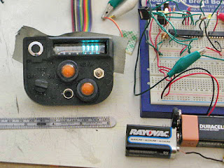 I can't CONTROL the VFD, but at least I can show it off. Here it is stuck in place with a bit of black gaffer's tape, hard-wired to display a row of "7"s. Yes, the filament voltage should be a current-controlled AC. But a small resistor is enough for this application. And, yes, the cathode really wants 30-60 volts. But it lights with 9, and looks decent with 18.
I've got both a DC-DC step-up and the parts to build a MOSFET-based boost converter on order, of course.
But now I'm in a quandary. I could wire up a static display like this, and get most of the rest of the buttons and horns working per spec, and box it up. I purchased some neodymium magnets to hold the top of the case on, which looks to be easier than affixing tiny brass screws into the 5mm plastic lip I have to work with.
I could even call that the prototype, and wait to put better electronics in a better pull (and probably a better mold) from the original master.
Or I could hold off for the driver, which should allow me complete control -- the chip I have on order is basically a 20-channel shift register good for up to 90 volts.
But either plan fails before knowledge that I start loading in a show next week. And I've got another show to run this weekend, plus meetings the next two days, and I really, really have to do some preparation and repairs for all of that.
As much as I hate it when I have to do it, I need to put the breadboard in a box, clear the work table for production soldering on other things, and haul it back out when things calm down. Even if they won't calm down until AFTER the deadline I've been trying to make.

At least this is better than the poor fellow who assembled the original "Timer" prop for the TV show "Sliders." He had so many display elements, he had to use fine wire-wrap wires to connect them all!
But, of course, the high-power shift register I have is a drain, not a source, and same goes for my new love, the ULN2803 Darlington Array. So I can't actually connect this thing properly until my new chips arrive in the mail.

And yes -- hard as it may be to see in the clutter of my not-at-all neat breadboarding, I am using one channel of the ULN2803 as an audio power amp! The source is a PWM pin on the Arduino, and simply writing "analogWrite (9, 120)" made for nice loud angry alarm tones. Later I'll code up some more siren-like swoops, and perhaps some Geiger Counter type clicks.


I've got both a DC-DC step-up and the parts to build a MOSFET-based boost converter on order, of course.
But now I'm in a quandary. I could wire up a static display like this, and get most of the rest of the buttons and horns working per spec, and box it up. I purchased some neodymium magnets to hold the top of the case on, which looks to be easier than affixing tiny brass screws into the 5mm plastic lip I have to work with.
I could even call that the prototype, and wait to put better electronics in a better pull (and probably a better mold) from the original master.
Or I could hold off for the driver, which should allow me complete control -- the chip I have on order is basically a 20-channel shift register good for up to 90 volts.
But either plan fails before knowledge that I start loading in a show next week. And I've got another show to run this weekend, plus meetings the next two days, and I really, really have to do some preparation and repairs for all of that.
As much as I hate it when I have to do it, I need to put the breadboard in a box, clear the work table for production soldering on other things, and haul it back out when things calm down. Even if they won't calm down until AFTER the deadline I've been trying to make.
Tuesday, October 9, 2012
Feeling stupid
Spent the entire productive part of the day putting a minimal Arduino on a breadboard. There's like, 12 components in total, and I still messed it up four times.
About the only thing I did right was to work step by step.
Built a 7805-based voltage regulator. Which didn't work. And turned out it was an old problem; my solderless breadboard doesn't continue the power strips the full length. So a couple of bridges, and now that's working. But if I hadn't put a "power on" LED I'd still be staring at a dead circuit...
Built the Arduino and it didn't fire up. Swapped the ATmega168 for a known good one with the "blink" program already loaded on it. And finally, after staring at the thing for an hour, realized I was holding the Reset low instead of high. And you don't actually need the pull-up resistor anyhow -- there's an internal pull-up on that pin.
Then hooked up the ISP and kept getting error messages. Stuck the ISP on to the ICSP header of a working Arduino and confirmed the tool chain was working. Was basically wiggling parts at random when I thought of pulling off the pin 13 LED. And that did it. So why isn't this necessary on a standard Arduino? What's different about my LED?
Well, finally got to the point where I could hook up the ULN2803 (Darlington Array) and proof the quick-and-dirty solution I had to lighting the VFD; to have it display "00000000, 11111111, 22222222...." And nothing. Until finally the niggling little memory of how I wired the robot came back to me and I realized the ULN2803 sinks, not sources!
Which means I can't even do the quick-and-dirty. Not on what I have.
While I wait for delivery of the Supertex HV5812P-G serial driver chips -- which I haven't even ordered yet -- about all I can do is confirm the LEDs that are going into the Dialight indicator light enclosures are nice and bright, and try to build a capacitance touch switch. Oh, and I guess I could write a simple look-up table for doing alpha-numeric on my seven-segment vacuum fluorescent display.
I would work on a boost converter, too, but I don't have a nice switching MOSFET or a Schotkey diode on hand. Nor does Radio Shack really have anything useful there.
Looks like this project won't be ready by East Bay Mini Makers Faire. And immediately following the fair I go into tech. Dangit. I could have made more progress if I had just a little more cash earlier on. Like the robot, I've had to make too many design compromises and too many gambles based on trying to work on too tight a budget.
It is a variation of the Sam Vimes Theory of Economic Injustice. When you are shy of capital, you have to proceed in ways that are actually more wasteful of funds. Worst case being, when you can't quite justify the safer, surer, but more expensive route, and gamble on the cheaper route -- which then fails, costing you as much as it would have just to go the expensive way in the first place.
Saturday, October 6, 2012
First Pull
A day of discoveries. More or less the concept for molding these things proofed. More or less.
 Not bad for a first-ever pull. I think the last casting I made was fifteen years ago, in some-one else's mold (it was an overnight repair of a show-critical prop, and fortunately the master mold was right there in the shop where I could find it.)
Not great, either, but actually I only need the one. The client has only ordered one box...the only real reason to cast is to be able to model in any material but deliver in sturdy resin.
 The master survived de-molding, too, with just a few dings. So I could in theory make up a better mold from it.
That was not something I could actually hope for. All my reading suggested that masters rarely survived coming out of a silicone mold, and this is a particularly fragile master, being mostly from lightweight floral-type foam, balsa, and wallboard spackle.
So here's lessons:
1) I'm sensitive to tin-cure silicone. The first mold I did made me rather nauseated -- enough to skip dinner that night. The second one, I worked right under a window and made sure not to hold the measuring or mixing cups too close. I still got a slight upset stomach, but not enough to make me skip lunch.
2) A small apartment is no place to be casting. I need to take this sort of thing to a shop space -- where there is good ventilation, where a spill doesn't mean I risk my cleaning deposit, and where I don't have to sleep next door to chemicals and dust.
But enough of enumeration. Back to essay style.
The first mold is actually a two-piece. Since the Shapeways print already had the desired thickness, it was pretty much cast one face, flip it over, slather the silicone with petroleum jelly as a mold release, cast the inside face. That worked pretty well, but....
a) The first pour was shy a few CC's and didn't end up with a level surface. This meant only mold stiffness held it flat when I cast.
b) The mold was a bit small for a box mold (I'm really, really broke and can't afford much silicone), and had no registration keys. When I did the first pull, one wall ended up being quite thin as a result. I should be able to firm it up with a little Bondo, tho.
c) Locating a thick pour spout on the inside wasn't the best idea. It was a pain to carve away once it was cast.
The second mold was a one-piece open-top box mold for a slush cast. What did I learn on this one?
a) I fixed the model to a slab of wood, and built a basswood box around it. But by "fixed," I mean with clay. And the master is so light, when all that silicone got into the box with it, the master floated right up! As a result I wasted a bunch of mold material under it, I had to cut a big nasty hole to release the master, AND the master ended up at an angle to the box thus some of the mold walls were very thin.
b) It takes more than you think. It took the entire starter kit of Oomoo to do these two molds. And it was still a little short. Fortunately I had some plaster I could square off the end with; that was the base after I flipped it over.
c) Yes, you can clamp wood together for the box, but it would be worth it to spend longer in carpentry and have a solid box that could be dissembled and re-assembled in exactly the same position. At least it didn't come apart on my mid-cast and spill resin all over the kitchen!
d) Smooth-cast 30 is not optimal for slush-casting.
 This is what the inside looks like. More slush than cast! Also quite heavy; I used up over half of the resin in the starter kit as well.
Fortunately all that has to go in here are the electronics, but I'd be way out of luck if I tried to make a battery door now. Well...I'd have to take a Dremel to it to chew a decent hole. And that would be messy. Very messy.
As I said, all I need is one, and even the electronics is a stretch goal. But given my budget, time, and the lack of funds to get yet more casting supplies, I may just back-burner casting the MEDKIT for a few weeks. Oh, and I really wouldn't mind taking a break from the chemicals for a while, too! I really, really, should not be messing with MEK (and spray paints, and superglue, and Bondo, and so on) in a small not-that-well-ventilated apartment!
Heck...once the next show is up and running, I might just drag my casting supplies over there and work on that during the day before a performance. Seeing as they got that robot from me labor-cost free (and the debris from that project is STILL kicking around here), I think they might owe me that much.
 I could always wave the master for the MEDKIT around, anyhow. Now that it has finally gotten shiny enough where I'm willing to call an end to the days of spackling and sanding.
That might even give me time to order some vinyl lettering for the controls. Although I kind of like the spooky effect of unlabeled controls.
 And delaying the MEDKIT also gives me the time -- and the funds -- to give Shapeways a little more love. Like the funky shape here in shiny stainless steel. This is the "treatment comes out here" part for the MEDKIT. Not to scale with the box models you see behind it; the largest dimension is barely 3 centimeters.
Shapeways could also knock out some new knobs in study metal, that I could tap so they would fit firmly on the shafts of the rotary switches.
Such useful services aside, I'm still horribly attracted by the idea of doing an electro-etch of custom graphics, then rubbing color into the metal. Because that's all I need now; to be electrolyzing metal and creating hydrogen in my apartment!

Not great, either, but actually I only need the one. The client has only ordered one box...the only real reason to cast is to be able to model in any material but deliver in sturdy resin.

That was not something I could actually hope for. All my reading suggested that masters rarely survived coming out of a silicone mold, and this is a particularly fragile master, being mostly from lightweight floral-type foam, balsa, and wallboard spackle.
So here's lessons:
1) I'm sensitive to tin-cure silicone. The first mold I did made me rather nauseated -- enough to skip dinner that night. The second one, I worked right under a window and made sure not to hold the measuring or mixing cups too close. I still got a slight upset stomach, but not enough to make me skip lunch.
2) A small apartment is no place to be casting. I need to take this sort of thing to a shop space -- where there is good ventilation, where a spill doesn't mean I risk my cleaning deposit, and where I don't have to sleep next door to chemicals and dust.
But enough of enumeration. Back to essay style.
The first mold is actually a two-piece. Since the Shapeways print already had the desired thickness, it was pretty much cast one face, flip it over, slather the silicone with petroleum jelly as a mold release, cast the inside face. That worked pretty well, but....
a) The first pour was shy a few CC's and didn't end up with a level surface. This meant only mold stiffness held it flat when I cast.
b) The mold was a bit small for a box mold (I'm really, really broke and can't afford much silicone), and had no registration keys. When I did the first pull, one wall ended up being quite thin as a result. I should be able to firm it up with a little Bondo, tho.
c) Locating a thick pour spout on the inside wasn't the best idea. It was a pain to carve away once it was cast.
The second mold was a one-piece open-top box mold for a slush cast. What did I learn on this one?
a) I fixed the model to a slab of wood, and built a basswood box around it. But by "fixed," I mean with clay. And the master is so light, when all that silicone got into the box with it, the master floated right up! As a result I wasted a bunch of mold material under it, I had to cut a big nasty hole to release the master, AND the master ended up at an angle to the box thus some of the mold walls were very thin.
b) It takes more than you think. It took the entire starter kit of Oomoo to do these two molds. And it was still a little short. Fortunately I had some plaster I could square off the end with; that was the base after I flipped it over.
c) Yes, you can clamp wood together for the box, but it would be worth it to spend longer in carpentry and have a solid box that could be dissembled and re-assembled in exactly the same position. At least it didn't come apart on my mid-cast and spill resin all over the kitchen!
d) Smooth-cast 30 is not optimal for slush-casting.

Fortunately all that has to go in here are the electronics, but I'd be way out of luck if I tried to make a battery door now. Well...I'd have to take a Dremel to it to chew a decent hole. And that would be messy. Very messy.
As I said, all I need is one, and even the electronics is a stretch goal. But given my budget, time, and the lack of funds to get yet more casting supplies, I may just back-burner casting the MEDKIT for a few weeks. Oh, and I really wouldn't mind taking a break from the chemicals for a while, too! I really, really, should not be messing with MEK (and spray paints, and superglue, and Bondo, and so on) in a small not-that-well-ventilated apartment!
Heck...once the next show is up and running, I might just drag my casting supplies over there and work on that during the day before a performance. Seeing as they got that robot from me labor-cost free (and the debris from that project is STILL kicking around here), I think they might owe me that much.

That might even give me time to order some vinyl lettering for the controls. Although I kind of like the spooky effect of unlabeled controls.

Shapeways could also knock out some new knobs in study metal, that I could tap so they would fit firmly on the shafts of the rotary switches.
Such useful services aside, I'm still horribly attracted by the idea of doing an electro-etch of custom graphics, then rubbing color into the metal. Because that's all I need now; to be electrolyzing metal and creating hydrogen in my apartment!
Friday, October 5, 2012
Oomoo Loomoo Gloopity-Gloo...
...I've got a couple questions for you.
One being, why am I doing this?
 Spackle, sand,
 Prime,
 Spackle again, sand again...
I'm not just getting bored with it, and a little frustrated that the surfaces are still far from pristine, but I'm also getting tired of dust everywhere, paint cans and spackle and putty and glue and sandpaper scraps everywhere, and still bits of foam and balsa and styrene everywhere as well.
And I'm worried, too. I finally found some molding rubber (after trying multiple art stores) and I've started my first pour:
 But I don't know how well it is going to work. I could even lose the master I've spent all week sanding.
(And, yes, that's not an effect of the camera. The oomoo looked well-mixed in the cup, but when I started the pour I could see it was still a little streaky. I can only hope it will still set up right! This in addition to worrying about release from the original, and how I'm going to make a proper two-piece mold, and if I've got enough silicone for all the pieces....)
For this project, it really would have been more economical (for money and certainly for time) to print the faceplate for the MEDKIT as well. And, possibly, print the body of the CBR kit. I'm still working out how to design the molds so I'll have a proper wall thickness and the pieces will fit together to make a single unit. I just don't patience to build a full battery door, at least not in the fragile masters.
And Shapeways is probably superior for another element, too; surface.
See, there is a real flaw in the way I design things. I contrast with, say, the typical Hollywood approach. Which is to say; you greeble it up. Whatever it is, it tends to have a lot of small meaningless surface detail. If they start with a real object, they hide it under big piles of added stuff.
This isn't always the way. It is more like a scale. Steampunk at one end. The many-litlte-bits of the Star Wars universe, and many game universes. Working through the more design-centric Star Trek. And in a few vehicles, you hit the modern era of real-world design; fluid, smooth shapes with fewer "lumpy" details.
Anyhow, for whatever reason, when I sketch out a design I tend to stay pretty close to Platonic forms. Well, more like silhouettes. Like the great cartoonists like Carl Barks taught, you want a shape that will read well in silhouette; that will be distinctive, that will have emotional associations. You might detail it up, but that strong shape should still read.
I do struggle to draw those kinds of shapes, but then when it comes to detailing, it seems I really don't. My robot had the same problem; it was one smooth glossy hemisphere, surmounted by two glossy bullet-shaped eye housings. So everything was spackle and smooth for days, even weeks.
These Morrow Project boxes are the same problem. Part of the issue is, of course, the same one the Hollywood prop builders face. Which is to say, hiding the fact that it is a model. If you've re-purposed a disposable razor, you want to alter it and detail it to hide the origin. If you've carved out of clay and wood, you want to hide the tool marks so it looks like a product of industry, not a cottage.
I swear, the next prop I build should be a fantasy dagger or magic item, so I don't have to work so hard to hide the tool marks!
Anyhow. The way this works out in the Morrow boxes is I'm trying to get the surfaces as flat as possible, with corners as defined and machine-like as possible. And that makes for a lot of frustration in time trying to clean up the shapes.
And makes it a better match for Shapeways.
(Still...printing the bodies of the boxes would be over a hundred bucks each. Although I suppose an interlocking top for easy assembly/dis-assembly, and/or a real battery compartment door, and maybe even rails to support the circuit board, are all wonderful advantages of doing it that way!)
De-molded the first piece. The Oomoo-30 set up just fine, and didn't react with the clay or the Shapeways print. Still not quite sure how to deal with the cut-outs -- break the mold there, or build up clay dikes, in which case they'd turn into giant plugs of resin... Also did a couple more smoothing passes on the MEDKIT faceplate and it is starting to look like something. So basically I'm a lot more happy with this project right now. It is even possible the CBR body will survive de-molding (but not likely -- that battery cover is going to be ugly. Unless I can get in there with toothpick and a lot of patience and seal it properly.)
I'm really coming around on the existing knobs I have, but if I do replace them, I think I will resin-cast around a salvaged brass insert. Of course that makes yet one more thing to purchase...along with olive drab paint, inductor for a high voltage power supply, screw terminals for the CBR, the mysterious "treatment" area as a stainless-steel Shapeways print, nameplates and/or custom vinyl lettering...
Now if only I had some income coming in.
One being, why am I doing this?


I'm not just getting bored with it, and a little frustrated that the surfaces are still far from pristine, but I'm also getting tired of dust everywhere, paint cans and spackle and putty and glue and sandpaper scraps everywhere, and still bits of foam and balsa and styrene everywhere as well.
And I'm worried, too. I finally found some molding rubber (after trying multiple art stores) and I've started my first pour:

(And, yes, that's not an effect of the camera. The oomoo looked well-mixed in the cup, but when I started the pour I could see it was still a little streaky. I can only hope it will still set up right! This in addition to worrying about release from the original, and how I'm going to make a proper two-piece mold, and if I've got enough silicone for all the pieces....)
For this project, it really would have been more economical (for money and certainly for time) to print the faceplate for the MEDKIT as well. And, possibly, print the body of the CBR kit. I'm still working out how to design the molds so I'll have a proper wall thickness and the pieces will fit together to make a single unit. I just don't patience to build a full battery door, at least not in the fragile masters.
And Shapeways is probably superior for another element, too; surface.
See, there is a real flaw in the way I design things. I contrast with, say, the typical Hollywood approach. Which is to say; you greeble it up. Whatever it is, it tends to have a lot of small meaningless surface detail. If they start with a real object, they hide it under big piles of added stuff.
This isn't always the way. It is more like a scale. Steampunk at one end. The many-litlte-bits of the Star Wars universe, and many game universes. Working through the more design-centric Star Trek. And in a few vehicles, you hit the modern era of real-world design; fluid, smooth shapes with fewer "lumpy" details.
Anyhow, for whatever reason, when I sketch out a design I tend to stay pretty close to Platonic forms. Well, more like silhouettes. Like the great cartoonists like Carl Barks taught, you want a shape that will read well in silhouette; that will be distinctive, that will have emotional associations. You might detail it up, but that strong shape should still read.
These Morrow Project boxes are the same problem. Part of the issue is, of course, the same one the Hollywood prop builders face. Which is to say, hiding the fact that it is a model. If you've re-purposed a disposable razor, you want to alter it and detail it to hide the origin. If you've carved out of clay and wood, you want to hide the tool marks so it looks like a product of industry, not a cottage.
I swear, the next prop I build should be a fantasy dagger or magic item, so I don't have to work so hard to hide the tool marks!
Anyhow. The way this works out in the Morrow boxes is I'm trying to get the surfaces as flat as possible, with corners as defined and machine-like as possible. And that makes for a lot of frustration in time trying to clean up the shapes.
And makes it a better match for Shapeways.
(Still...printing the bodies of the boxes would be over a hundred bucks each. Although I suppose an interlocking top for easy assembly/dis-assembly, and/or a real battery compartment door, and maybe even rails to support the circuit board, are all wonderful advantages of doing it that way!)
De-molded the first piece. The Oomoo-30 set up just fine, and didn't react with the clay or the Shapeways print. Still not quite sure how to deal with the cut-outs -- break the mold there, or build up clay dikes, in which case they'd turn into giant plugs of resin... Also did a couple more smoothing passes on the MEDKIT faceplate and it is starting to look like something. So basically I'm a lot more happy with this project right now. It is even possible the CBR body will survive de-molding (but not likely -- that battery cover is going to be ugly. Unless I can get in there with toothpick and a lot of patience and seal it properly.)
I'm really coming around on the existing knobs I have, but if I do replace them, I think I will resin-cast around a salvaged brass insert. Of course that makes yet one more thing to purchase...along with olive drab paint, inductor for a high voltage power supply, screw terminals for the CBR, the mysterious "treatment" area as a stainless-steel Shapeways print, nameplates and/or custom vinyl lettering...
Now if only I had some income coming in.
Thursday, October 4, 2012
Dead Oomoo
Is this progress?
I prepped the Shapeways printed faceplate for casting...both to save a back-up of a part that took not just fifty bucks to print, but a whole day to clean, and to practice molding on something simpler than the box.

Jolly King plasticine clay that must have been in the bottom of my Art Supplies box for decades (I switched to oven-hardening Fimo that long ago). And a jolly time reading up to find out if it was sulfur-based and otherwise compatible with my Silicone molding rubber. And even more time re-reading tutorials and the Prop-Makers handbook and planning how I was going to make the molds.
The (large) check for equipment rental I was expecting last Friday still hasn't come in, nor has the funds from selling off some old gear cleared PayPal. So I used the very last of my cash to buy plastic cups (to measure and mix the molding and casting compounds) and petroleum jelly (as a mold release).
At which point I found out I'd totally forgotten Oomoo has a shelf life. My nice big bottles of Oomoo-30 silicone casting rubber were nice big perfect interior casts of the bottles they came in.
More or less at the same time (you have to multi-task if you don't want to be wasting days sitting around waiting for paint to dry), I'd decided the vacuum fluorescent display sat too deep in the display hood to look right.
So I pried the top off the box and carved deep into the thing:

Until I had the display looking a little closer to how I wanted it:

And then started rebuilding the curves and reinforcing the now rather chipped balsa:

The standard formula Apoxie doesn't appear to grip balsa well until it is completely cured. Unfortunately that lets out the golden carving time; when it is firm enough to get good detail but still soft enough you can carve into it with an X-acto knife. Once it is completely set up it is about the hardness of soap stone...and over the next few days arrives at something a lot like granite.
So in my eagerness to get the shape re-refined, I'm trying some super-white instead (which otherwise is not my favorite).
At least I got one thing finished: I decided against any inset for the injector port. So that means finishing off the battery is the last task before the final coat of paint. There are still some random little divots and seams but I've spent long enough on this one!

(Okay...maybe a couple of panel lines or something on the battery. And perhaps some lettering..although I'd love to see if vinyl letters will stick to the mold, thus allowing me to cast them as incised letters...)
Wednesday, October 3, 2012
Paint a little, sand a little, cheap cheap cheap!
(Sung to a tune from "The Music Man.")
The boxes are taking shape. The usual round of refining; spackle up gaps, sand carefully, paint with primer. See new gapes, spackle them, sand them, give it another coat of primer. Eventually I was down to wet-sanding with 220, and that's where I'm going to leave this one.
I may put a couple more details in. A finger notch above the "battery" (which is actually just a groove in the surface). Perhaps inset the "injector port" (which for the CBR is an LED in a rather medical-looking chrome bezel). But I'm a little afraid to try to make a neat inset oval carving into the curve surface that is already there (and took so much time and so many steps to smooth). Perhaps I'll just dremel one into the first casting, where it will be easier to fix.
This is assuming the pull goes okay. It has been a loooong time since I did any casting, and I don't believe I ever did latex casting. At the worst case, I could even ruin the master and have to start from scratch. Which would be really annoying.
So before that, pictures:

CBR on the left, getting the final (I hope!) divots filled. Med-Kit on the right, with a lot of shaping and smoothing still to go.
As I've said before, I wish I had a table saw. Or a full shop. Or a ShopBot. Working with hand tools, it seems smartest to carve from the lightest materials -- balsa and foam, instead of MDF or basswood. But that makes these very fragile, and I spend a fair amount of time just filling pores.
I didn't know if these lightweight materials would actually make it, or if I could make those curves, or if I was going to end up dropping another hundred bucks at Shapeways to print the whole body. Thus, no progress pics.

The CBR has two curves, both inspired from the one and only drawing in the Morrow Project official game literature. The front is rounded over at a generous radius. And then at the back is a roughly major-limb-diameter curve -- "Apply Med Kit Directly to Forehead." Err, "...Wound." The most annoying part of the CBR was actually that little cut-in corner, where the terminals to connect up the external siren go.
Harder to see (because I had it printed in Black Detail), is the top of the CBR kit.

And this is them posing; the CBR with the printed top (the components have yet to be mounted in the holes), and the Med Kit in the bag the original came in.
The core of the CBR is one big block of foam. Then sheets of styrene were cut to size and glued on every side. Then a whole bunch of filling -- with mostly wall spackle -- to smooth out the joins. The Med Kit is, on the other hand, built around an actual US Army bandage-and-aspirin box, with balsa for the flat parts, foam for the curve, and apoxie sculpt for the sunshade around the display.
I'm still of two minds about which was easier; printing the weird cut-outs, or carving them. Carving is annoying and long and I'm a little worried about how I'm going to cast it and be able to have the right shaped space to stick the VFD in. Printing was an annoying amount of fiddling to make a mesh that was dimensional and watertight and printable. But as a result it has nice flat surfaces, square corners, plus it is an exact and known thickness, making mounting buttons and lights easy.
Well, we'll see how it goes. By this time tomorrow the latex mold for the first one should be curing. And now I'm off to read Thurston James AGAIN (plus I'm now following a second amazing prop-maker here on Blogger.)
Tuesday, October 2, 2012
Getting Nowhere at a faster pace
Been accomplishing things this week. But so far it hasn't improved my life much. It is unusually hot for this climate, and my house is infested by otherwise innocuous little black flies...they are only annoying due to their vast numbers, and their affinity towards any liquid I leave out...coffee, soup, wet paint...
My Shapeways order arrived monday and if not for the custom knob it looks like I really need (the shape of the knobs I have are just wrong for it), I'd have the box physically done by early next week. Electronically, I'm not sure how long it might be. Not so much because of breadboard time, soldering and debug time, and programming time, but because I may need a few parts I don't have, and they aren't the sort of things I can pick up at the local Radio Shack.
I started carving the box, finally (the top is a Shapeways print, as it is more complex and has raised lettering/graphics.) And that is going well enough that, assuming the molding step goes well, I'll be able to make the second box without paying for another Shapeways print. Actually, the print price isn't bad. But I'm more shy of money than I am of time -- though neither are good.
I still wish I had a shop. These boxes would be a lot easier to start if I had a table saw. And was otherwise set up to use MDF or basswood. Instead I'm cutting them from balsa, sheet styrene, and this rather fragile carving foam I bought a few months back at the art supply store. Can't say I'm thrilled by the stuff. The toughest part about getting these boxes right is they have to be exactly dimensional -- they have to fit the printed top. The other tough part is they need to look, well, not like they were carved from foam. Which means smooth sides, right angles, and completely flat surfaces.
I rented some of my sound gear and the client came to pick it up Monday. Annoyingly, without the check. Turns out the company decided to move their offices over the weekend and no paperwork got processed. I also managed to sell off two of my old synths on eBay. Within hours of listing them...I should have set a higher "buy it now!" I shipped today. But, annoyingly, the eBay/PayPal system is to freeze the deposit until delivery. Which meant there was nothing in my PayPal account to cover the UPS charges. Which meant going into my very small bit of cash -- which was an advance to cover the expenses of building the props. At least there was still enough cash left to get some casting resin. But not enough for paint.
I also worked a one-day show so there is more coming in. Plus I'm already on contract for two shows and busy doing research and making meetings for one of them. Which doesn't pay until opening night. A PARTIAL payment. A SMALL one.
Still, by early November I'll be finally seeing daylight on finances. Until then, I can't afford credit card payments or my gym membership, I can barely afford food, and of course I can NOT prioritize over food and overdue bills and art supplies to finish my paying work to pick up even one tiny can of FREAKING BUG SPRAY!
(Seriously...other things are going pretty well, and I have left-over food from the gala stuck in the fridge so I won't starve, but those little bugs are really starting to annoy me!)
Subscribe to:
Comments (Atom)