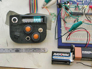
Is this progress?
Soldered many, many wires on to the Vacuum Fluorescent Display module. Next time I do a project like this, I'm getting a display that has a serial backpack already included.
At least this is better than the poor fellow who assembled the original "Timer" prop for the TV show "Sliders." He had so many display elements, he had to use fine wire-wrap wires to connect them all!
But, of course, the high-power shift register I have is a drain, not a source, and same goes for my new love, the ULN2803 Darlington Array. So I can't actually connect this thing properly until my new chips arrive in the mail.
Instead I worked on other circuit elements. This is a sound test; a 3" speaker is dangling inside the case from those wires.
And yes -- hard as it may be to see in the clutter of my not-at-all neat breadboarding, I am using one channel of the ULN2803 as an audio power amp! The source is a PWM pin on the Arduino, and simply writing "analogWrite (9, 120)" made for nice loud angry alarm tones. Later I'll code up some more siren-like swoops, and perhaps some Geiger Counter type clicks.
More Arduino tricks. That's just an LED in a nice looking chrome bezel bought for a couple bucks at All Electronics. Then there's a 1 meg resistor, and the Capacitance Sensor library from the Arduino Playground. And it triggers nice and accurately, too...even running off battery with no ground to call its own.
I can't CONTROL the VFD, but at least I can show it off. Here it is stuck in place with a bit of black gaffer's tape, hard-wired to display a row of "7"s. Yes, the filament voltage should be a current-controlled AC. But a small resistor is enough for this application. And, yes, the cathode really wants 30-60 volts. But it lights with 9, and looks decent with 18.
I've got both a DC-DC step-up and the parts to build a MOSFET-based boost converter on order, of course.
But now I'm in a quandary. I could wire up a static display like this, and get most of the rest of the buttons and horns working per spec, and box it up. I purchased some neodymium magnets to hold the top of the case on, which looks to be easier than affixing tiny brass screws into the 5mm plastic lip I have to work with.
I could even call that the prototype, and wait to put better electronics in a better pull (and probably a better mold) from the original master.
Or I could hold off for the driver, which should allow me complete control -- the chip I have on order is basically a 20-channel shift register good for up to 90 volts.
But either plan fails before knowledge that I start loading in a show next week. And I've got another show to run this weekend, plus meetings the next two days, and I really, really have to do some preparation and repairs for all of that.
As much as I hate it when I have to do it, I need to put the breadboard in a box, clear the work table for production soldering on other things, and haul it back out when things calm down. Even if they won't calm down until AFTER the deadline I've been trying to make.


No comments:
Post a Comment