There has been a push since at least the Industrial Revolution to offload the rote work -- the repetitive, mindless tasks -- onto machinery. The Maker revolution dotes on this, and my personal props work has paralleled; moving to technologies that let me copy and paste details instead of sculpting them individually, using mills and other power tools to achieve desired surfaces instead of hand-smoothing them, etc.
The downside, though, of getting rid of as much of the mindless drudge work as possible, is you don't have mindless drudge work to do when you are tired, sick, it is hot and you just got off a long day's work, you only have an hour before you need to go off and do something else, etc.
I'm looking at a big task list for the Holocron orders right now. Sure, there's some sanding and patching, and some soldering. Those are mindless; I sanded the last one over a couple evenings while watching YouTube.
But before I can even tear into the stack of orders I need to fix a couple remaining issues. I need to do the next round of PCB corrections in Eagle CAD. I need to edit the new solution to the USB jack into the laser SVG's. I need to dial in the sensitivity on the sensor and write a couple of new functions into the software.
None of this is stuff I can do when sleepy or when my head is fuzzy or when I'm distracted. None of them can I do without several consecutive hours to look through the change orders, re-familiarize myself with the parts/functions/software/layers etc., and still have the time to take careful caliper measurements and run tests and otherwise make sure the work is being done accurately. I can't throw any of this at the wall in hopes it will stick. It requires a free day (or at least a free afternoon) with health and no major distractions.
I can't even make up the rest of the stack of version 1.0 PCBs. Because before I can get to the relatively mindless rote of soldering in the discrete components I have to delicately place the surface mount and run a reflow oven cycle. That takes the kind of steady hand that does not come after the fourth cup of coffee and in any case requires a free hour or more for setup and cleanup.
The line continues to move, of course. Code crunching is increasingly moving to automation now. PCB is automated (if you like the results, which I don't). But of course that merely amplifies the problem. Because then the work that needs to be done so the project can progress is the intense concentration of original insight and artistic thought.
And, yeah, you can (and I've been forced to, on more than one theatrical design contract) reach into your bucket of trite old ideas, recycled ideas, and stolen ideas. And the people around you will still coo and aw about how creative you are.
But it isn't as good and it really doesn't feel right. Every single lighting design I've done for theater has involved me spending at least two hours doing nothing but sitting in a chair in the auditorium staring at the set. My average is a week of back-burner, of thinking off and on about the show, making scribbles, re-reading the script, etc., until the idea finally comes.
Fortunately, that kind of necessary percolation does seem to be entirely compatible with being tired, sick, busy, hot, whatever. It just needs the world to spin a few times before the ideas are ready to take full form.
Showing posts with label Eagle. Show all posts
Showing posts with label Eagle. Show all posts
Thursday, November 10, 2016
Sunday, September 25, 2016
The light went out!
Alternative title (for those who don't remember Ralph Bashki's Wizards); "Hey! Who turned out the lights!" (One of the freakiest Doctor Who monsters ever!)
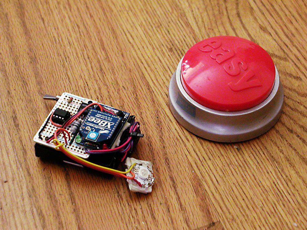
I tested the load sharing and charge circuit on my new board. The battery I had been using for testing was pretty badly drained and after waiting two hours it was a relief to see the "charge" light finally go out. Means the schotkey and MOSFET are doing their jobs correctly. Next up is install it in a holocron for a lighting test. Then write some quick-and-dirty code to test the user option buttons.
Taking a step back, this is a big change in how I do electronics. I was just window-shopping at Adafruit and I realized I don't see myself needing any protoboard soon. Or even a lot of hookup wire. I've pretty much moved over to PCBs.

To recap, this is the process of the Holocron circuit I'm testing now;
1) Drew up the schematic in EAGLE
2) Ordered parts, mostly from Digikey
3) Drafted the board in EAGLE
4) Sent the EAGLE files out to OSHpark, a board making company.
5) When all the mail had arrived, stuck the smaller parts on the board with a syringe of paste and then put the board into my T-962 to solder them all at one go.
6) After the board cooled, hand-soldered larger components like the USB jacks.
7) Attached my Adafruit USBtinyISP to the new board's header, and flashed the on-board CPU with the software I'd written in the Arduino IDE.
8) Test and install
The first disjunct from how I did things as a teen is although I still have a big parts box, I don't use it unless I've made a mistake or need to test something or are too impatient. For the most part, I spec out the exact components I need and find them through the parametric sorting system at Digikey.
Digikey is very friendly towards small orders, and has a huge catalog. What makes it navigable is their parametric system; the usual method is to drill down, specifying the most important values first and winnowing down the choices.
The next big change is going to printed circuit boards. There are a number of fab houses now that will do small prototype runs for cheap. So I do a lot less of assembling components on protoboard (although that still has its place). PCBs allow me to make a denser, more compact board, they offer much higher reliability, they are faster, and lastly, they are the only practical way to include surface-mount components.

EAGLE is the key tool here. There are other programs to draft PCBs. EAGLE has a hobby version that is essentially full-function (just restricted in board size and layer count). It also has a schematic editor, and the nifty thing is, board and schematic are automatically linked. So the software will ensure you route your copper traces to make exactly the same connections as are shown in the schematic.
There are software tools out there to simulate the circuit itself. I haven't used those yet. Schematic is helpful enough. The big trick with EAGLE is parts libraries. There are many libraries contributed by users (the big hobby vendors like Spark Fun and Adafruit have libraries for most of the parts they sell) but I'm afraid not all the footprints are trustworthy. So the trick with EAGLE is to slowly build up your own unique library of trusted parts, parts you have personally verified on a PCB you have made. Fortunately, the EAGLE editor is odd, but useable; I've several personally created parts that have now been tested in production.

It is quite possible to hand-solder surface mount (some crazy people even hand-solder the seemingly impossible, like BGA components). Faster, neater, and more electrically sound results come from reflow soldering. Basically you put a specially formulated paste of microspheres of solder in a flux base on the board, plop the components on top, and then carefully bring it to a calculated temperature over a carefully timed interval so the solder melts, flows, and then hardens correctly.
The software-controlled infrared heat lamp of my T-962 reflow oven does this quite nicely (many people have improved their T-962's, many others have made their own out of toaster ovens and microcontrollers).

And then I'm in the Arduino infrastructure. Arduino is basically a wrapper (you could even think of it as training wheels) around the AVR series of microcontrollers. I spent a while learning how to write straight C code and shove it into a "naked" AVR chip using avrdude, but the main thing that experimenting has left me with is an alternative to a working USB connection on my boards.
All I need is a six-pin header and I can plug in a USB adaptor I have. And after that, with some exceptions, I write Arduino-style code. The Arduino IDE is another piece of freeware. It is a bare-bones coding program, with essentially no advanced tools. But for the 8 KB of software I'm putting into a Holocron brain, it is enough. It's rather like the good old days of writing HTML pages in a text editor...

It took a few years to get all the pieces of this toolchain into place, but now I have it, doing electronics has largely moved for me from squinting at poorly-labeled parts, tacking them in place with random bits of colored wire and hoping, to a largely computer-aided process executed on the laptop.
Which is a lot like much of my props-making now. I'm making still-increasing use of laser cutting, which translates 2D CAD (actually, Illustrator -- and actually, I use the freeware Inkscape despite some ongoing file conversion woes) into precise cuts in the material. And 3d printing, naturellement.
I tested the load sharing and charge circuit on my new board. The battery I had been using for testing was pretty badly drained and after waiting two hours it was a relief to see the "charge" light finally go out. Means the schotkey and MOSFET are doing their jobs correctly. Next up is install it in a holocron for a lighting test. Then write some quick-and-dirty code to test the user option buttons.
Taking a step back, this is a big change in how I do electronics. I was just window-shopping at Adafruit and I realized I don't see myself needing any protoboard soon. Or even a lot of hookup wire. I've pretty much moved over to PCBs.

This is actually the previous version, plus my first-ever surface mount PCB
To recap, this is the process of the Holocron circuit I'm testing now;
1) Drew up the schematic in EAGLE
2) Ordered parts, mostly from Digikey
3) Drafted the board in EAGLE
4) Sent the EAGLE files out to OSHpark, a board making company.
5) When all the mail had arrived, stuck the smaller parts on the board with a syringe of paste and then put the board into my T-962 to solder them all at one go.
6) After the board cooled, hand-soldered larger components like the USB jacks.
7) Attached my Adafruit USBtinyISP to the new board's header, and flashed the on-board CPU with the software I'd written in the Arduino IDE.
8) Test and install
The first disjunct from how I did things as a teen is although I still have a big parts box, I don't use it unless I've made a mistake or need to test something or are too impatient. For the most part, I spec out the exact components I need and find them through the parametric sorting system at Digikey.
Digikey is very friendly towards small orders, and has a huge catalog. What makes it navigable is their parametric system; the usual method is to drill down, specifying the most important values first and winnowing down the choices.
The next big change is going to printed circuit boards. There are a number of fab houses now that will do small prototype runs for cheap. So I do a lot less of assembling components on protoboard (although that still has its place). PCBs allow me to make a denser, more compact board, they offer much higher reliability, they are faster, and lastly, they are the only practical way to include surface-mount components.

Perfboard construction. Even protoboard is neater (and faster) than this!
EAGLE is the key tool here. There are other programs to draft PCBs. EAGLE has a hobby version that is essentially full-function (just restricted in board size and layer count). It also has a schematic editor, and the nifty thing is, board and schematic are automatically linked. So the software will ensure you route your copper traces to make exactly the same connections as are shown in the schematic.
There are software tools out there to simulate the circuit itself. I haven't used those yet. Schematic is helpful enough. The big trick with EAGLE is parts libraries. There are many libraries contributed by users (the big hobby vendors like Spark Fun and Adafruit have libraries for most of the parts they sell) but I'm afraid not all the footprints are trustworthy. So the trick with EAGLE is to slowly build up your own unique library of trusted parts, parts you have personally verified on a PCB you have made. Fortunately, the EAGLE editor is odd, but useable; I've several personally created parts that have now been tested in production.

Again this is the previous version. This is most of the layers turned on in the EAGLE display; top copper, bottom copper, silkscreen...
It is quite possible to hand-solder surface mount (some crazy people even hand-solder the seemingly impossible, like BGA components). Faster, neater, and more electrically sound results come from reflow soldering. Basically you put a specially formulated paste of microspheres of solder in a flux base on the board, plop the components on top, and then carefully bring it to a calculated temperature over a carefully timed interval so the solder melts, flows, and then hardens correctly.
The software-controlled infrared heat lamp of my T-962 reflow oven does this quite nicely (many people have improved their T-962's, many others have made their own out of toaster ovens and microcontrollers).

The hat is not essential to operation. A couple of fire bricks from my brazing days, however, are; it blows some pretty hot air out the bottom when in use.
And then I'm in the Arduino infrastructure. Arduino is basically a wrapper (you could even think of it as training wheels) around the AVR series of microcontrollers. I spent a while learning how to write straight C code and shove it into a "naked" AVR chip using avrdude, but the main thing that experimenting has left me with is an alternative to a working USB connection on my boards.
All I need is a six-pin header and I can plug in a USB adaptor I have. And after that, with some exceptions, I write Arduino-style code. The Arduino IDE is another piece of freeware. It is a bare-bones coding program, with essentially no advanced tools. But for the 8 KB of software I'm putting into a Holocron brain, it is enough. It's rather like the good old days of writing HTML pages in a text editor...

The main window of the Arduino code editor -- showing some very un-Arduino like code; these are direct register calls basically written in bog-standard C.
It took a few years to get all the pieces of this toolchain into place, but now I have it, doing electronics has largely moved for me from squinting at poorly-labeled parts, tacking them in place with random bits of colored wire and hoping, to a largely computer-aided process executed on the laptop.
Which is a lot like much of my props-making now. I'm making still-increasing use of laser cutting, which translates 2D CAD (actually, Illustrator -- and actually, I use the freeware Inkscape despite some ongoing file conversion woes) into precise cuts in the material. And 3d printing, naturellement.
Saturday, June 25, 2016
Waiting
Dropped some extra bucks on Amazon to get them to ship the last part of my order. The oven has been here for days:

(No, it doesn't come with the hat. It also didn't come with the Kapton tape I ordered, but tracking says I'll finally get that today.)
The components have been here for a while (Digikey is fast, as is Adafruit):


And I picked up a set of Thomastik Alphayue's. Which means for some people I've just given the game away on the new instrument...currently tracked to arrive Monday, and I'm having a heck of a time waiting for it!

(No, it doesn't come with the hat. It also didn't come with the Kapton tape I ordered, but tracking says I'll finally get that today.)
The components have been here for a while (Digikey is fast, as is Adafruit):

And the new board arrived yesterday from OSHpark:

So far everything seems correct. The footprint for the USB connector is slightly wrong but still fits -- I'll need to fix my Eagle library part. On the down side, it is larger than I was envisioning. Yes, I had measurements, but I didn't make a test cut-out. I was more concerned about having enough room to clear traces and be able to reach the SMDs to place and solder them.
Well, looking at it now, I'm comfortable with compacting it quite a bit. And changing over the larger SMDs (1206 size) to 0805's. Or possible even 0603's (those sizes only really hold for resistors, but it's a pretty good guideline to how small you are getting).
At least I've finally figured out how to translate the sketches I've been making for the Holocron diffusion layer into black and white (the laser engraver will respond to gray-scale information, but on acrylic the results aren't usually worthwhile):

And I picked up a set of Thomastik Alphayue's. Which means for some people I've just given the game away on the new instrument...currently tracked to arrive Monday, and I'm having a heck of a time waiting for it!
Saturday, June 11, 2016
USB...A
What did I say earlier about "gotchas?" Well, this time it wasn't an unknown unknown. It was a perfectly-well known unknown.
I was cleaning up the silkscreen on my latest PCB. Couldn't get the SMD-type USB connector to look nice. But while I was working on it...I realized I'd never checked it against the actual sourced part. Which, upon examination of the engineering drawings, turned out to be...a through-hole. Serves me right for putting a part on there I hadn't personally vetted!
So once again into the mysteries of Eagle part creation.
And when that was done...realized this would be the first circuit I've made in years that doesn't have a blinkenlight for power status. I know; if it is working right, it will have a stack of neopixels for display. But that little status LED is just so durn handy for diagnosis...so back to the CAM files to stick another pair of 1206 SMDs in one of the remaining available corners.
You know what? Those 0805's don't look so scary anymore. I think this will be the last board I do with the larger SMDs. And if stencil and reflow go well, then...FTDI and beyond!
And the board passed the DRC -- with some modification of two of the thermal pads/polygon fills -- and the order placed at OshPark. Now I just have to see if I have the budget left for the parts...and move on to working out the new art for the laser!
Sunday, June 5, 2016
Riding Thermals
Show is over, and Holocron board is routed. Now I just need to add fill polygons and thermal vias to help with the heat around the charge circuit components, run the Design Rules checks, clean up the silkscreen, and generally inspect and clean up all the layers preparatory to sending out to the fab house.

Haven't decided if it is worth doing a few parts with syringe and soldering iron or just go straight into solder stencil and reflow oven. I'll be doing more boards, and I'm committed to using a lot more SMDs going forward. This one's basically populated with 1206's and SOT-23's, plus some through-hole parts, but the Wraith Stone is going to go down to at least 0806 if not 0603's.
Not that I've really built up my Eagle library yet. Only a few parts on this board are verified footprints (aka, I already had a board fabbed with them and everything worked).
I may even start putting an FTDI chip on my Arduino compatibles. It's only a 20-pin SMD, not even fine-pitch.
Saturday, June 4, 2016
Chapter Adverse

Not the PCB itself; I have some realism! I need to play with heat profiles and thermal vias, double-check footprints, and of course clean up the silkscreen...and I haven't even routed the board yet.
So of course I'm taking a short break to think about the next chapter in the fanfic.
If I had a proper outline, I'd have a pretty good idea what had to happen in each chapter. The same exercise, after all, takes place fractally within each chapter, within each scene, down to the line of dialog or sentence of description.
As an example, in my last chapter I had a "bit" I wanted to do; Alister gets talked into learning how to shoot, but unexpectedly turns into one of those gun collector types who go into raptures about Broad Arrows and Suicide Sears. This framed out as a series of snapshots where he brings more and more unusual guns out to the shooting range. A number of "beats," to use that useful bit of theater terminology. I needed Alister getting a bad start, Alister trying a different gun, Alister bringing out the first unusual gun, and finally Alister talking glibly about his latest unusual gun. As it worked out, I built those beats around several specific handguns; a SIG-sauer P226, a Colt Police Positive, a Whitney Wolverine, and a Nambu Type 14. With a Gyrojet for the payoff gag later.
Between those scenes would be more dry history lesson, so I'd planned to send some mooks into the manor and have a nice knock-down fight to finish the chapter on a high note. Except that this parallel structure, in which each Alister scene was followed by three other scenes, drove my page count too high.
This is the problem of writing serial style. I know where I'm going and approximately how long it is going to take, but the details I'm figuring out only a chapter or two ahead.
So now the exercise is looking at how many "beats" there are in the fight, and seeing if these stretch out to fill a chapter, or if I have to add other business. And there's another problem. Once the fight is over I've got several revelations I can make, and that will pad out the page count, but I don't want the climax of the chapter to occur around the middle.
For pacing reasons, then, I'm contemplating having the discussion of who the heck Amanda is while the armed men she has sent are still crawling around the manor looking for the Wraith Stone. And there's the planning at the moment. I have "bits," but I don't have beats. Daniel has to talk a mook down. Teal'c has to show off his mastery of the manor's hidden passageways, and the gyrojet needs to be taken down from the mantlepiece and fired a few times.
Once I've broken it into beats, and arranged and interleaved them in a way that supports the overall arc of the chapter, I can do a little division and see how close I will make it to my target word count this time.
And it is midnight, and I still feel awful, but the schematic is almost finished -- just need to add the resistor ladder for the function buttons, the resistor for the capacitance sensor, and a couple more decoupling and power smoothing capacitors. Oh, yeah, and figure out a footprint for the mercury tilt switch I managed to score on eBay.
Tuesday, April 19, 2016
Tilt
Ah, this is the point where it becomes engineering. I've threshed out options for the Holocron to come up with a compromise that meets the primary requirements of being cheap and easy to assemble. Now it is just about nailing down the specifics as I generate the final files; EPS files to cut the shell, Eagle files for the PCB, and of course a BOM for all the parts and materials.

But it doesn't mean that discoveries have stopped. Far from it. First there was the discovery that USB can't safely deliver the power to run my first-choice of LED. Then more exploration; if downstream devices negotiate for power, what is the typical draw of a USB thumb drive (and is it going to interfere?)
Yesterday I tried to look up the typical value for a pull-up resistor on the RESET line of the AVR chip I was using. And after scrolling though several massive threads on StackExchance and AVRFreaks, I've learned that resistor is hotly contested but, in the end, omitted as often as not.
And today I was looking at options in tilt switches and discovered that the previous holocron I made was running said part well outside of spec. Typical current handling of these devices is 1 to 5 mA! So basically you use them as sensors, not as a power switch.

So I thought a little about building my own (several Instructable pages are out there showing this), or about putting a weight on a lever switch. But, really, it seems an equally sensible design to leave it off entirely, instead tasking the capacitance sensor for turning the lights off and simply letting it run the battery down (until you plug it into a USB charge source again). Okay -- I might put a toggle on the inside anyhow.
Oh, yes, and there was a long bit of research to see if 1-pin capacitive sensing, with or without ATmel's own libraries, was going to work. The Capsense library in the Arduino Playground uses up two digital pins, and with an ATtiny45 I was already scarily short of pins. Which also meant yet more reading up to see what the drawbacks were of putting circuit loads on the MOSI, MISO, and other programming pins. (And yet more long, heated discussions to read at StackExchange).

But in the end, it makes more sense to provision with the ATtiny84; not only does it separate all these pins, not only does it provide some extra pins for the end-user to get creative with their own sensors. but it then becomes more of a legitimate fork of the ATtiny84-based Cree driver board I was working on before.

Of course it isn't necessary to go through all this merely to light a holocron. You can just stick an LED on a resistor and either put some batteries inside or cut up a USB cord. The intent here is for full RGB light which is selectable and animatable (aka pulsing, flickering, color swirl effects), and for operation fully unplugged with painless recharging. Oh, and the option to add a user-supplied USB memory device inside, making it a practical desktop accessory.
To achieve all that and keep the costs down, I'm pushing what was hand-wiring and various (mostly Adafruit) boards on the prototype into one custom PCB.
Another sideline I keep wandering down is the temptations of a custom-written GUI to control the thing. I only discovered recently that the HID standard is bi-directional, allowing the host computer to send messages to the hosted device. Which can be done even on the through-hole AVRs (even ATtinys) via V-USB, saving you from having to go through surface-mount soldering. Even though SeeedStudio offers that as a service now.
(Actually, I may go surface-mount with more parts than the necessary Lithium Polymer charge management chip, to save space. But the cool thing about the HID fork of the USB standards is HID is allowed to be low-speed without breaking the USB standard. And they are driverless!)
In any case, I'm going with the dreaded VCR Programming paradigm on this one. Because I can put three or four buttons in a small space and set them up as Select, Enter, and Decrement/Increment. And the advantage of this over an analog potentiometer is that this has memory; you start from wherever the value was last set instead of going to wherever the potentiometer was left. (And the advantage to me is I can tie them all to a single analog input pin with a simple resistor ladder).
(And as I wrote the above, I realized a rotary encoder would also serve. And you can get a quadrature-encoded one from Bourns for about a buck fifty. Hrm. Yet one more thing to make a determination on as I try to move to final PCB layout.)

Paper-doll trial layout in Fritzing
But it doesn't mean that discoveries have stopped. Far from it. First there was the discovery that USB can't safely deliver the power to run my first-choice of LED. Then more exploration; if downstream devices negotiate for power, what is the typical draw of a USB thumb drive (and is it going to interfere?)
Yesterday I tried to look up the typical value for a pull-up resistor on the RESET line of the AVR chip I was using. And after scrolling though several massive threads on StackExchance and AVRFreaks, I've learned that resistor is hotly contested but, in the end, omitted as often as not.
And today I was looking at options in tilt switches and discovered that the previous holocron I made was running said part well outside of spec. Typical current handling of these devices is 1 to 5 mA! So basically you use them as sensors, not as a power switch.

I want to do all this one did, but with a lot less mess.
So I thought a little about building my own (several Instructable pages are out there showing this), or about putting a weight on a lever switch. But, really, it seems an equally sensible design to leave it off entirely, instead tasking the capacitance sensor for turning the lights off and simply letting it run the battery down (until you plug it into a USB charge source again). Okay -- I might put a toggle on the inside anyhow.
Oh, yes, and there was a long bit of research to see if 1-pin capacitive sensing, with or without ATmel's own libraries, was going to work. The Capsense library in the Arduino Playground uses up two digital pins, and with an ATtiny45 I was already scarily short of pins. Which also meant yet more reading up to see what the drawbacks were of putting circuit loads on the MOSI, MISO, and other programming pins. (And yet more long, heated discussions to read at StackExchange).

From ArduinoCC
But in the end, it makes more sense to provision with the ATtiny84; not only does it separate all these pins, not only does it provide some extra pins for the end-user to get creative with their own sensors. but it then becomes more of a legitimate fork of the ATtiny84-based Cree driver board I was working on before.

Eagle file of the prototype Cree driver board. Which is also used in the Retro Raygun!
Of course it isn't necessary to go through all this merely to light a holocron. You can just stick an LED on a resistor and either put some batteries inside or cut up a USB cord. The intent here is for full RGB light which is selectable and animatable (aka pulsing, flickering, color swirl effects), and for operation fully unplugged with painless recharging. Oh, and the option to add a user-supplied USB memory device inside, making it a practical desktop accessory.
To achieve all that and keep the costs down, I'm pushing what was hand-wiring and various (mostly Adafruit) boards on the prototype into one custom PCB.
Another sideline I keep wandering down is the temptations of a custom-written GUI to control the thing. I only discovered recently that the HID standard is bi-directional, allowing the host computer to send messages to the hosted device. Which can be done even on the through-hole AVRs (even ATtinys) via V-USB, saving you from having to go through surface-mount soldering. Even though SeeedStudio offers that as a service now.
(Actually, I may go surface-mount with more parts than the necessary Lithium Polymer charge management chip, to save space. But the cool thing about the HID fork of the USB standards is HID is allowed to be low-speed without breaking the USB standard. And they are driverless!)
In any case, I'm going with the dreaded VCR Programming paradigm on this one. Because I can put three or four buttons in a small space and set them up as Select, Enter, and Decrement/Increment. And the advantage of this over an analog potentiometer is that this has memory; you start from wherever the value was last set instead of going to wherever the potentiometer was left. (And the advantage to me is I can tie them all to a single analog input pin with a simple resistor ladder).
(And as I wrote the above, I realized a rotary encoder would also serve. And you can get a quadrature-encoded one from Bourns for about a buck fifty. Hrm. Yet one more thing to make a determination on as I try to move to final PCB layout.)
Sunday, March 1, 2015
Gah Software
In Star Wars (the first film, the original film, which is to be known as "Star Wars," period) a small farming homestead purchases a droid that can speak Bocce -- purchases a functional AI because that's easier than learning the computer language some of their old evaporators use.
Meanwhile on Next Generation and later, everyone can use everything that has microcircuits, and there's never even a moment of realizing the docs are all in Klingon or whatever. I think Star Wars gets it a lot closer.
Anyhow.
I've been really sick for a couple of days. And spent it delving into some software I haven't used in far too long. Still learning my way around GIMP, getting better with Inkscape -- and flipping back and forth between those two with great rapidity as I develop the most recent iteration of the Holocron:
 This image is watermarked because the art for this one I want to keep exclusive to the client that ordered it.
And I'm pretty much volunteering the design time, but aside from the vector on the center image, it is all re-purposable for the holocron kits I'll be offering soon at the RPF.
I'm going to be able to offer a fair number of customization options right off the rack, plus option to do new design work as I find time.
Perhaps I'll even some time solve the assembly issue. I've seen some Holocron designs that use a staggered outer edge to hide the way the shell has to be assembled: and those would not need to be sanded and painted.

Anyhow. Figured out an option for the DuckLight battery issue and rigged up a quick test with the prototype; hooked the main circuit to regulated 5v, and plugged the Cree into a separate 4-cell battery pack. It seems to deliver almost the output I achieved with an overall regulated 500ma power supply.
So the scheme now is to add a 3.3v LDO to the PCB. It won't be that wasteful of space; I already need to add the filter capacitors to stabilize the ATtiny.
Pity there's no easy way to cram that in to the current PCB so I could do some proper in-place prototyping. But the boards were only ten bucks.
 For completely random reasons, I spent most of my sick time messing around with a software I'd started to forget. Poser. Poser 9, to be precise, which saves all the parts of the interface that worked badly in Poser 6, and adds flash-driven menus that work poorly, non-scalable interface fonts, and other nice little details that make it excruciatingly inefficient and frustrating.
It's worse than that. I also flip into Poser 6 when I'm rigging a prop, because it is simpler to work in and makes cleaner files.
And for some stuff, DAZstudio is a little easier. At least the camera is superior. But of course the interface is entirely different, in almost every way it can be.
I'm really not looking forward to having to go back into Carrara, but I have some modeling projects in the pipeline that need it. Well, that or Blender...and I'm still having terrible trouble coming to grips with Blender.
 Even Fusion 360. Some of the specific curves and edges I need out of it are far too difficult to
achieve inside the interface. So like pretty much everything else I do, I need to flip the meshes into another application to do some work, then re-import them.
And I just realized it has been several months since I last used that software. They've probably changed the entire thing by now!
At least EagleCAD was a relatively small learning curve, and shouldn't take too long to pick up again...
Meanwhile on Next Generation and later, everyone can use everything that has microcircuits, and there's never even a moment of realizing the docs are all in Klingon or whatever. I think Star Wars gets it a lot closer.
Anyhow.
I've been really sick for a couple of days. And spent it delving into some software I haven't used in far too long. Still learning my way around GIMP, getting better with Inkscape -- and flipping back and forth between those two with great rapidity as I develop the most recent iteration of the Holocron:
And I'm pretty much volunteering the design time, but aside from the vector on the center image, it is all re-purposable for the holocron kits I'll be offering soon at the RPF.
I'm going to be able to offer a fair number of customization options right off the rack, plus option to do new design work as I find time.
Perhaps I'll even some time solve the assembly issue. I've seen some Holocron designs that use a staggered outer edge to hide the way the shell has to be assembled: and those would not need to be sanded and painted.
Anyhow. Figured out an option for the DuckLight battery issue and rigged up a quick test with the prototype; hooked the main circuit to regulated 5v, and plugged the Cree into a separate 4-cell battery pack. It seems to deliver almost the output I achieved with an overall regulated 500ma power supply.
So the scheme now is to add a 3.3v LDO to the PCB. It won't be that wasteful of space; I already need to add the filter capacitors to stabilize the ATtiny.
Pity there's no easy way to cram that in to the current PCB so I could do some proper in-place prototyping. But the boards were only ten bucks.
It's worse than that. I also flip into Poser 6 when I'm rigging a prop, because it is simpler to work in and makes cleaner files.
And for some stuff, DAZstudio is a little easier. At least the camera is superior. But of course the interface is entirely different, in almost every way it can be.
I'm really not looking forward to having to go back into Carrara, but I have some modeling projects in the pipeline that need it. Well, that or Blender...and I'm still having terrible trouble coming to grips with Blender.
Even Fusion 360. Some of the specific curves and edges I need out of it are far too difficult to achieve inside the interface. So like pretty much everything else I do, I need to flip the meshes into another application to do some work, then re-import them.
And I just realized it has been several months since I last used that software. They've probably changed the entire thing by now!
At least EagleCAD was a relatively small learning curve, and shouldn't take too long to pick up again...
Tuesday, February 3, 2015
Begosh
The first PCBs arrived from OSH Park:

I partially populated one (nothing's soldered yet) to check if the footprints I designed in Eagle matched the parts I ordered from Digikey. So far, so good. Except that the key part -- the current limiters -- are coming via "International Airmail" from Fasttech and there is no tracking available.
Assuming the AMC7135's work -- which is really what this board is intended to test -- I already have a few ideas towards the next iteration. Probably drop the breadboard spacing for the outer pins, go to a lower profile trim pot and switch to SMT for the LEDs as well (so I can add more blinkenlights -- serial data, the traditional "pin 13 LED" of Arduino compatibles, and of course keep the power light.)
And I haven't quite figured out the best format for the XBee backpack (plus I keep searching for more budget-conscious alternatives to the XBee).
Here's what the board replaces:

That's the quick-and-dirty vero board version I made for the radio light. Only two channels on this one, as I was mixing red and green LED for a sort of amber light. That toggle you see is hot-glued to the side of a AAA battery pack. At least this iteration had the ICSP header, making it a little less annoying to tweak the software.
It was sitting inside this prop:

(Dress rehearsal photograph made by Anna Kaminska for Actor's Ensemble). Also taken before I replaced the ailing previous circuit with one that could reliably generate a decent amber.
So, sure, the new circuit is smaller, and as fast as I am with the vero board (or, rather, the somewhat expensive but totally worth it "Perma-Proto" stripboard from Adafruit) having already wired and partially programmed versions should make it a lot easier to add it to productions.
But more than that -- with wiring and programming already in place and basic options available just by turning a knob and hitting a button, this should be useable by people who don't have the time and experience to learn all this stuff themselves.
I partially populated one (nothing's soldered yet) to check if the footprints I designed in Eagle matched the parts I ordered from Digikey. So far, so good. Except that the key part -- the current limiters -- are coming via "International Airmail" from Fasttech and there is no tracking available.
Assuming the AMC7135's work -- which is really what this board is intended to test -- I already have a few ideas towards the next iteration. Probably drop the breadboard spacing for the outer pins, go to a lower profile trim pot and switch to SMT for the LEDs as well (so I can add more blinkenlights -- serial data, the traditional "pin 13 LED" of Arduino compatibles, and of course keep the power light.)
And I haven't quite figured out the best format for the XBee backpack (plus I keep searching for more budget-conscious alternatives to the XBee).
Here's what the board replaces:
That's the quick-and-dirty vero board version I made for the radio light. Only two channels on this one, as I was mixing red and green LED for a sort of amber light. That toggle you see is hot-glued to the side of a AAA battery pack. At least this iteration had the ICSP header, making it a little less annoying to tweak the software.
It was sitting inside this prop:
(Dress rehearsal photograph made by Anna Kaminska for Actor's Ensemble). Also taken before I replaced the ailing previous circuit with one that could reliably generate a decent amber.
So, sure, the new circuit is smaller, and as fast as I am with the vero board (or, rather, the somewhat expensive but totally worth it "Perma-Proto" stripboard from Adafruit) having already wired and partially programmed versions should make it a lot easier to add it to productions.
But more than that -- with wiring and programming already in place and basic options available just by turning a knob and hitting a button, this should be useable by people who don't have the time and experience to learn all this stuff themselves.
Saturday, January 24, 2015
Laser Rifles and Dying Fairies
Not, not "Wizards, The Musical" (which one day, in some other life, I would love to have a part in producing).
I took a short job in The City -- for low enough pay a third of it is going to pay BART fare -- and once again an application came up for a DuckLight. Which is currently in the form of a PCB being manufactured in China. That is, the prototype board is. I figure there's about a 50% chance the first board will actually work correctly.
Once again, I would have saved a lot of time if I could have just reached into my kit and pulled one out. But also, once again, I hadn't imagined anything like this application until it came long.
Tinkerbell. There's a spot in the musical where Tink needs to go into her little house and stay there for a while. I had already planned for one of the default animations on the DuckLight to be a flicker or shimmer, but I didn't even know why I wanted that. Now I do. Dial up a nice Tinkerbell green and the effect is half-way there.
 Only half-way, because this production is children's theater. No onstage actor is going to be able to hit a switch. So it needs the next element, the next board up in my Eagle-and-fab list; the XBee backpack.
Well, I did pull a morning of very swift soldering, and set up a single-channel AVR-controlled Cree and attached an XBee to it in line-passing mode. There was some strangeness going on with lines floating or automatically resetting or something but by adding a double-click detect I finally got it reliable enough to use it over the closing performances.
 Otherwise Tink is being played by a laser. Which still makes me uncomfortable, even though I opened up the beam focus until the power is much spread out. To hit his targets the follow-spot operator went and attached the laser to three-foot long stick of wood that he braces against his shoulder. Naturally I took to calling this contraption his "Laser Rifle."
Being one of the bargain bulk optical goods from the industrious young engineers in Shanghai, this particularly laser diode is not stable enough, cooled enough, or otherwise suitable for leaving on for longer than a few seconds at a time. As a stop-gap, I put an AVR-powered switch on it that randomly blinks it off for half a second or so every few seconds. That seems to help, but I'm betting I'll still be out a laser diode before the show closes.
The blinking looks quite natural and Tink-like. Particularly tonight's performance. Right after Wendy said, "Wouldn't you say so, Tinkerbell?" the light blinked several times in quick succession as if Tink was making an acerbic reply.
 Here's the full circuit in better light, by the way:
The 8-pin dip is the ATtiny85 running the random blink routine. The Tip-120 switches laser power, with a blinkenlight wired in parallel as a status monitor. Another one monitors the battery connection, which is switched on and off by the momentary button. That's the nice thing about these AVR's; supply power, and it boots up softly in milliseconds and starts running the program loop.
This was all in all another informative show. I need that serial Xbee connection for reliable triggering, and this makes twice now that 3 watts of RGB was a little marginal. Unfortunately the jump to 10 watts of LED power brings in a whole new level of current regulator and thermal management complexity.
I took a short job in The City -- for low enough pay a third of it is going to pay BART fare -- and once again an application came up for a DuckLight. Which is currently in the form of a PCB being manufactured in China. That is, the prototype board is. I figure there's about a 50% chance the first board will actually work correctly.
Once again, I would have saved a lot of time if I could have just reached into my kit and pulled one out. But also, once again, I hadn't imagined anything like this application until it came long.
Tinkerbell. There's a spot in the musical where Tink needs to go into her little house and stay there for a while. I had already planned for one of the default animations on the DuckLight to be a flicker or shimmer, but I didn't even know why I wanted that. Now I do. Dial up a nice Tinkerbell green and the effect is half-way there.
Only half-way, because this production is children's theater. No onstage actor is going to be able to hit a switch. So it needs the next element, the next board up in my Eagle-and-fab list; the XBee backpack.Well, I did pull a morning of very swift soldering, and set up a single-channel AVR-controlled Cree and attached an XBee to it in line-passing mode. There was some strangeness going on with lines floating or automatically resetting or something but by adding a double-click detect I finally got it reliable enough to use it over the closing performances.
Otherwise Tink is being played by a laser. Which still makes me uncomfortable, even though I opened up the beam focus until the power is much spread out. To hit his targets the follow-spot operator went and attached the laser to three-foot long stick of wood that he braces against his shoulder. Naturally I took to calling this contraption his "Laser Rifle."Being one of the bargain bulk optical goods from the industrious young engineers in Shanghai, this particularly laser diode is not stable enough, cooled enough, or otherwise suitable for leaving on for longer than a few seconds at a time. As a stop-gap, I put an AVR-powered switch on it that randomly blinks it off for half a second or so every few seconds. That seems to help, but I'm betting I'll still be out a laser diode before the show closes.
The blinking looks quite natural and Tink-like. Particularly tonight's performance. Right after Wendy said, "Wouldn't you say so, Tinkerbell?" the light blinked several times in quick succession as if Tink was making an acerbic reply.
The 8-pin dip is the ATtiny85 running the random blink routine. The Tip-120 switches laser power, with a blinkenlight wired in parallel as a status monitor. Another one monitors the battery connection, which is switched on and off by the momentary button. That's the nice thing about these AVR's; supply power, and it boots up softly in milliseconds and starts running the program loop.
This was all in all another informative show. I need that serial Xbee connection for reliable triggering, and this makes twice now that 3 watts of RGB was a little marginal. Unfortunately the jump to 10 watts of LED power brings in a whole new level of current regulator and thermal management complexity.
Wednesday, January 21, 2015
Lot of work for so little pay
Inventoried stock and ordered the remainder for the next round of Stage Lights. Also reminded the purchaser I was barely covering expenses on them and soon I'd have to charge more.
Struggled some more with parts libraries in Eagle. The software has been through some changes recently and some of the more common suggestions found online no longer work. But I got it together and sent off an order for the first try at a board to OSHpark.
Inventoried my Aliens Grenade supplies, made up an order for new material, and sat down with a bunch of snapcaps and shotshells to check dimensions. Watching snippets of the movie again. I am increasingly of two minds about my design.
There's almost a fanon when you get to stuff like this; how it may have actually looked in the movie, and how prop-makers are tending to make them look these days. Aliens has a bit of that; the original Pulse Rifles were painted brown, but they read olive drab under the lighting of the movie. So which is more accurate? The actual color of the prop, or the color the prop appeared in the movie?
In the case of the grenades, there are sadly few high-resolution images, and few documented screen-used with decent images available. So one could make in a sense two different arguments; one for what the prop-makers probably provided, and what is therefor most accurate to a world in which a film was made about a bunch of space marines. And one for what is just at the verge of visibility, possibly hidden in blur and lighting effects; the world in which Weyland-Utani managed to get a bunch of them killed on a remote colony world.
In re the outer world, I have more than strong suspicions that the grooves were made with a thread-cutting tool, and are probably v-shaped. The spring-loaded trigger, of which there were unlikely more than one or two to begin with, was top-loaded. The nose is a simple chamfer and there is no "nose ring." And the cap was off-white, painted in various colors (seemingly red, dark blue, a rather washed-out green, and perhaps one or two in yellow), with a strip of teflon plumbing tape or a hand-painted white line. Oh, yes; and I have reason to believe there was a fairly large cut-out in the bottom, with the primer sticking out like a very short lamp post.
In the inner, diagetic world, these have more distinction in their markings. My head canon is that originally the caps were shaped differently to reflect the various loads, and as well some of the bodies are distinctive. Manuals and other materials were released on the basis of those models, but in the usual business of military contract bidding they ended up sharing molds and the items issued at the time of the film had lost some of those distinctions. And furthermore, GI's of any generation are playful, and once they found out the protective caps were interchangeable, would start putting them on randomly in whatever suited their own color/fashion sense.
And at some nearly orthogonal angle to either of these directions of approach, are the prop-maker's aesthetics. The major reason to keep those in mind is because one cosplayer may have props from more than one supplier. And more than one cosplayer may appear in the same picture. So if everyone is making their M51A's a bright baby blue, it makes a certain sense to follow suit.
The major elements found in fan-made grenades are however varied. Some have the tree-stump firing pins, others look more shotgun-like. Some have chamfered noses, some have rounded noses. However, almost all have squared-off grooves.
Which leaves me basically floundering between two untenables; follow the best guess of the best information and end up with a result that doesn't meet expectation: or do what fulfills my personal aesthetic judgment and is somewhat defensible both diagetically and historically -- but only somewhat, as the design combines elements I can not be sure of with elements I am reasonably certain are wrong.
Oh, yes. And I also got another reweld mentioned at me. A ZB-30, which from a brief look appears insane.
Monday, January 19, 2015
CAD Woes
Trying to get the PCB ordered on my prototype "DuckLight." The first Eagle layout looked pretty good, but it seemed possible to shrink the board's footprint until it was only 2xAAA wide. Which you can run on, but it runs the LEDs a little cold.
Anyhow, I shrunk the layout and ran traces by hand. I was also conscious of the potential difficulties in soldering SMDs so I made a point of holding the traces far outside of the pads of those parts. So that took a couple of evenings. But got it down to one via (well, I also ended up omitting a duplicate VCC on the second header. It would have required multiple vias in order to get the connection.)
I used a part with internal connections (a tactile switch) as a jumped in one spot, and Eagle kept flagging it. So I went to the forums for the first time with a question. And it turns out not only have lots of people asked about this, there is no current solution.
But then I went to order the parts to make sure the ones in the CAD were actually available stock. I'd used the SparkFun Eagle library in several places, and you'd think this would be a shoe-in, right? But no. The part in their library doesn't actually have an analog in their store.
They did have something in their store that I could modify the package to, however. And after a bit of struggling re-routing around the new (and larger) dimensions, I had confirmation of available parts.
The final DRCs, and Eagle starts throwing up mask errors. Turns out that, yes once again, many of the library parts I was using have a silkscreen that goes over the copper traces. Which can be a problem at smaller fab houses that don't have the software to fix this on the fly. So back once again to the package designs, now to edit all the silkscreens.
Nice of various people to make libraries available to everyone, but really, could they adhere a little closer to reality?
Subscribe to:
Comments (Atom)