This week was tech for another show at the crazy people. I got some kind of mystery bug and collapsed on the floor. I plead to be taken off the show, but they couldn't find a replacement. The day after I collapsed, I pulled a nine-hour shift that went until midnight, and I didn't have a bite of food for twelve hours. The day after was longer, and then the weekend included an early-morning performance on the first day of Daylight Saving.
One of the cast was so exhausted he slept through his alarm clock and barely made it to the building in time for his entrance. I was so dead I was shaking...really operating on automatic pilot and hoping the buttons I was pushing were the right ones. Ears were so stuffed up I couldn't hear the show properly (the poor booth design doesn't help), and so it was all a big ball of blind trust and frustration.
But that horror is over (well...next performance is even earlier in the morning, but I have to week to catch up on rest and food.) So I'm back to learning how to program miniature computers.
Why? Well, the ideas I've been having for stuff to stick into props (lasers, sound chips, servos, etc.) all seem to require a bit of computing power to pull off easily. Arduinos are wonderful, but they are at least 30 bucks a pop and take up a bit of space. The heart of an Arduino, however, is a tiny chip that can be had for as little as a couple of bucks and is available in as small as an 8-pin dip (okay...there are smaller packages in SMD, but I meant the smallest package an ordinary person can solder to!)
The AVR also holds out the chance of me taking my MIDI devices in new directions, particularly my holy grail; MIDI-over-USB. My eye right now is on an ATMEGA32U breakout board, but Adafruit is currently out of stock and I've had to back-order.
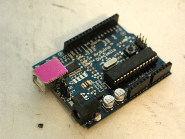
Here's an Arduino, taken on my desktop this morning without any attempt at nice lighting or anything. You can see the USB port and DC power jack at the lower left. Along the sides are the headers which can take pins, naked wires, or support an entire "shield" (a second board that sits on top of the Arduino).

Here's a naked AVR. This is an ATtiny13, one of several available in an 8-pin dip.

This is my bare-bones programming board. The clock, power, MISO and so forth are brought out to a standard 6-pin programming header. There is also an LED on one pin and a button on another to help with trying out basic code examples. The AVR chips run better with regulated power, external clock crystal/resonator, power supply buffering, pull-down resistors etc, but as this programming board shows they can also run on a bare battery and the internal oscillator and no other components.

This is the ISP I am using. On one end, USB port. On the other, plugs for the two standard ISP headers. When I'm writing AVR code, the ISP is powered off my laptop and the AVR is powered from the ISP.

This is a breakout board for one of the surface-mount AVRs -- in this case, an AT90USB. Unlike the Arduino, it uses an AVR with native support for USB, and thus there is no FTDI chip on the board. It does contain a bootloader to allow it to accept fresh code over USB, but unfortunately the bootloader support software doesn't run on my old Mac. At some point this week I'll break out the MISO et al and add a standard ISP header to it.
Anyhow. I got through "Hello World" a while back. But I was not particularly satisfied. Although I'd managed the difficulties of the AVR tool chain (AVRDUDE, avr-gcc, the USBtinyISP, Make, and so forth) I didn't entirely understand the code I was using.
This got worse when I added a button to my bare-bones programming board and tried to learn how to do the "World says hello back" exercise. I had to read a button state, and change the LED state when I saw it.
In the Arduino IDE (the free development environment) dealing with the physical input and output pins are broken out into several rather self-explanatory macros.
To do the task I described above, the Arduino syntax is something like:
int foo = 0;
pinMode (1, INPUT);
pinMode (2, OUTPUT);
digitalWrite (2, LOW);
void loop()
{
foo = digitalRead(1);
if (foo = HIGH)
{
digitalWrite (2, HIGH);
}
}
In AVR libC, setting the I/O preferences (and turning the LED off) for the pins looks like this:
DDRB = 0x02;
PORTB |= (0 << 2);
You can imagine my confusion! For day after day I looked at different examples, and I simply could not logic out how one command was able to set multiple pin modes.
Finally the shoe dropped. I'd been seeing the term "register" over and over again, as in "output registers," but I thought of it as a vagary of nomenclature. Finally I realized what was happening. The status (direction, as well as other important things like setting a pull-up resistor, or writing a value to a pin) is carried in, well, a byte. A byte in a specific storage spot in memory. A register.
Now, I'd learned the basics of Assembly once. Writing down close to the bare metal, I thought of registers as being accumulators; they held numbers that math was being done to. It just didn't occur to me how perfectly sensible it was to write and store all sorts of other important operational data into the form of a register. (Heck, when I was writing Assembly on the Z80, I was leveraging the environment for I/O -- aka I was sending print commands out to the BIOS of CP/M).
Another confusion was in the mnemonics being used. In the AVR series, there are several registers that store what in the Arduino IDE is so helpfully called "pinMode." These are the Data Direction Registers, and are suffixed A, B, C, etc. Thus, "DDRB" is the (only) register controlling pin mode on the ATtiny13 and ATtiny45 AVRs; the 8-pin miniatures I've been programming on.
Just to make things even more confusing, there are not necessarily 8 pins being controlled by each register. On the AVRtiny13/45, there are 6 I/0 pins known as 0, 1, 2, 3, 4, 5 and they are spread about in patchwork pattern around the VCC and ground and so forth.
Here's the easy way to think of the DDRn; as a set of flags. Setting a bit to 0 sets the corresponding pin as an input, and setting the bit to 1 sets the corresponding pin to be an output.
This didn't make me feel stupid when I finally figured it out, but perhaps it should have. Way back when I wrote my own version in BASIC of the famous old teletype Star Trek game. This is the one where each "sector" in the quadrant (or was that quadrants in the sector?) was a 16 x 16 alphanumeric array, with asterixs for stars, an E for the Enterprise, and K for those nasty Klingons. When I wrote my game, I created a 1-dimension array of string variables; each string held the number of starbases, the number of Klingons, and the number of Enterprises (well, actually, it was a flag whether the Enterprise was there or not).
Now that I know what I know now, I might have used a single byte instead of re-inventing the wheel. Each place in the binary representation would be a flag. "00000001," for instance, would represent a sector in which one of the possible "slots" for a Klingon vessel was filled.
Counting zeros is no fun. This is why in the example I gave above of C code for the AVR, although "DDRB = 0b00000010" is completely legitimate, most people translate it into hexadecimal for easier reading. Thus, "DDRB = 0x02"; the first pin mode is set to input (as are most of the others, including the ones that don't exist), and the second pin is set to be an output.
But what in heck does "PORTB |= (0 << 2)" mean? Okay, once you've figured out the nature of I/O registers, it becomes clear that PORTn is the register where you send data you want to be expressed on the output pins (it also is the register that, if a pin is set as an input, turns on the internal pull-up resistor). The problem is I usually skipped over the "how to do basic math" section in my C textbooks, especially including bitwise operators. I mean....why would I ever need to work in raw binary? Turns out, this is why. Imagine you've turned on one LED by writing a command like "PORTB = 0x02." Now you want to turn on a second LED on pin 3. Writing "PORTB = 0x03" won't work; that is binary for "00000010" and won't turn on the pin you want. But writing "PORTB = 0x04" isn't right, either. Because when "00000100" arrives at the register, it turns on the LED on pin 3....and turns off the LED on pin 2.
You could write an if...then statement to evaluate whether the pin 2 LED was on, and then pick whether to write "PORTB = 0x04" or "PORTB = 0x06", but there is a simpler way. You want to perform a binary addition.
Using the command "bitwise OR" which in C is "|", you construct something like "PORTB |= 0x04" which performs a bitwise OR between the existing contents of PORTB and your new value.
Or, if what you want to do is just talk to a single pin and not try to remember anything else about the content of the register, use "PORTB |= (1 << 3)" This shifts a 1 three places, into the pin we wanted, and then bitwise ORs the result with the existing PORTB. Using the other bitwise operators in C, we can also set a single bit, or clear a single bit; in each case, the bit we want to act on is shifted into position to create a bitmask which is then combined with the existing value using a bitwise operator. I had a handy chart of these but I managed to lose it. If I am understanding them correctly,
PORTB |= (1 << 4) sets bit 4.
PORTB ^= (1 << 4) flips bit 4.
PORTB &= -(1 << 4) clears bit 4.
And, of course, if you want to turn on all the bits (or turn them off) you can skip the bit shift operation. And if you don't care about preserving any previous bits, then just write the exact pattern you want as "PORTB = 0xA3"
An aside. I sometimes wonder about explaining to Benjamin Franklin what is going on inside something as seemingly simple as a pocket calculator (does anyone still have pocket calculators?) Explaining an LED properly would be a bit of a chore, considering you practically have to get into quantum mechanics. But anyhow! It is tough enough explaining even to a reasonably technical modern person what is going on when one programs a micro.
I have right now on my desk my test board. As of this morning, it contained a single LED and a button. Push the button and the LED lights up. It doesn't seem that useful, or that complicated. Making an LED light with the push of a button can be accomplished with a sophisticated instrument known as a piece of wire.
But that's how such things are. The principles that will in some later project, pulse and color-change LEDs and flash lasers and run servos to designated positions and play back sounds all in perfectly timed sequence are all incorporated in the principles of getting an LED to flash when a button is pressed.
And what is the actual sequence here?
Well. I am writing code on my laptop. Which is to say, I am typing on an electronic keyboard, writing data onto volatile memory and into a hard disk (a tiny piece of magnetic material spinning at high speeds under exacting computer control). This data is translated through various abstractions on multiple levels of my computer's operating system to finally show up as bitmap representations of alphanumeric characters on a pane of liquid-crystal material which I can then see.
When I have finished this document encoded as ASCII text, I turn to an application program reached through the UNIX command line, "make," which in turn calls a patched version of the GNU compiler, avr-gcc. The compiler breaks down the C code described by the letters and numbers I wrote, figures out how to get it to run on an AVR, and then translates it into opcodes which can be understood by the AVR. Then make takes over again, and turns the compiled code into binary form which can be sent to the actual chip.
Next I turn to AVRDUDE, the programmer provided by Atmel (AVR Downloader/UploaDEr). This is software that negotiates an available serial connection to the actual AVR chip. I am using a third-party programmer available in kit form from Adafruit which attaches to my laptop's USB port. So the data from that binary make created goes through multiple changes in voltage and format, with all sorts of annotation by various buffers and handshake protocols and so forth, until it reaches the chip.
The AVR itself -- an AVRtiny45 at the moment -- has various internal hardware and software that figures out how to write the new code into the onboard FLASH memory (non-volatile RAM) without killing itself in the process. Stuff like this is always a bit of a Baron Munchhausen process, cutting out the middle of the rope you are climbing down to tie it on to the end.
As its last act, the AVRs internal loader starts the program running. Now, all the opcodes that were sent over in binary that got translated from the original ideas in C are sent to the intelligence at the heart of the chip, where it executes different operations. The AVRs are RISC chips, meaning a Reduced Instruction Set, and they are also modified Harvard Architecture, meaning program space and arithmetic space are mostly kept separate (the AVR can, of course, use program code to write program code, performing a true Munchhausen operation. One of the things many people have done is to move the USB protocols and the external programmer inside, allowing the AVR to be programmed with nothing but a length of cable. Unfortunately, that also takes up a big chunk of the rather limited program memory space).
The opcodes tell the chip to tell parts of itself to move bits around in the internal registers, which eventually filters down to setting either a high voltage state or a low voltage state on a number of latching transistors. Millions of these transistors, working together, show up as the internal architecture of the chip, with clock, timers, buffers, power switches, and various other things besides.
And at the end of it, what do you have?
In the simplest terms, the chip changes the state of one or more outputs based upon a combination of time and the state of zero or more inputs (it would be "zero or more outputs" but then you wouldn't be able to tell the chip was doing anything, right?)
Which again doesn't sound like much, until you realize how much complexity can be built on these tiny steps. Rather like the immense complexity of the entire process built on nothing but millions of simple junctions in doped regions of a silicon substrate.
As one simple example, take time.
My day's progress has been in learning about the AVRs internal timers. It has several. At the moment, my LED is flashing without the button. It is doing so because one of the internal timers is counting, and a simple bit of code is detecting when it reaches a threshold and toggles the LED when it does. I haven't quite figured out the proper reset though, so I'm doing that in code.
The timers can also output their value as a PWM position. Instead of setting a number in a register, the timer can set the pulse width on a pin. Which can be used to dim an LED. Still doesn't sound so useful, until you realize that dimming a constant-voltage device is non-trivial. It "dims" by switching the LED on and off thousands of times a second, and achieves a specific intensity by varying the length it is ON versus the length it is OFF.
Since this is under control of an internal timer that is independent of the program cycle, the LED can be set to a specific intensity and left there while other code runs. That other code might, say, change the value of the counter on a regular basis; the result is the LED pulses. Or, if more than one PWM pin is used, and a tricolor LED substituted, the code can then specific which of the millions of possible colors the LED will shine in combination. And change THAT, over time.
Plus, PWM is used to drive servos. The pulse width is directly translated to servo position via a data line independent of the power line. Unlike a motor, a servo can be powered from some higher voltage but the AVR can tell it "go to this position and hold there, waiting for further orders."
Moving on from a simple counter "blink" to full PWM is my next learning project. More or less at the same time, I'll also be learning how to use interrupts. These, too, are independent of the program flow.
I'm tempted to explain interrupts more fully, especially as they relate to the nature of AVR programs, but this essay is way too long already.
No comments:
Post a Comment